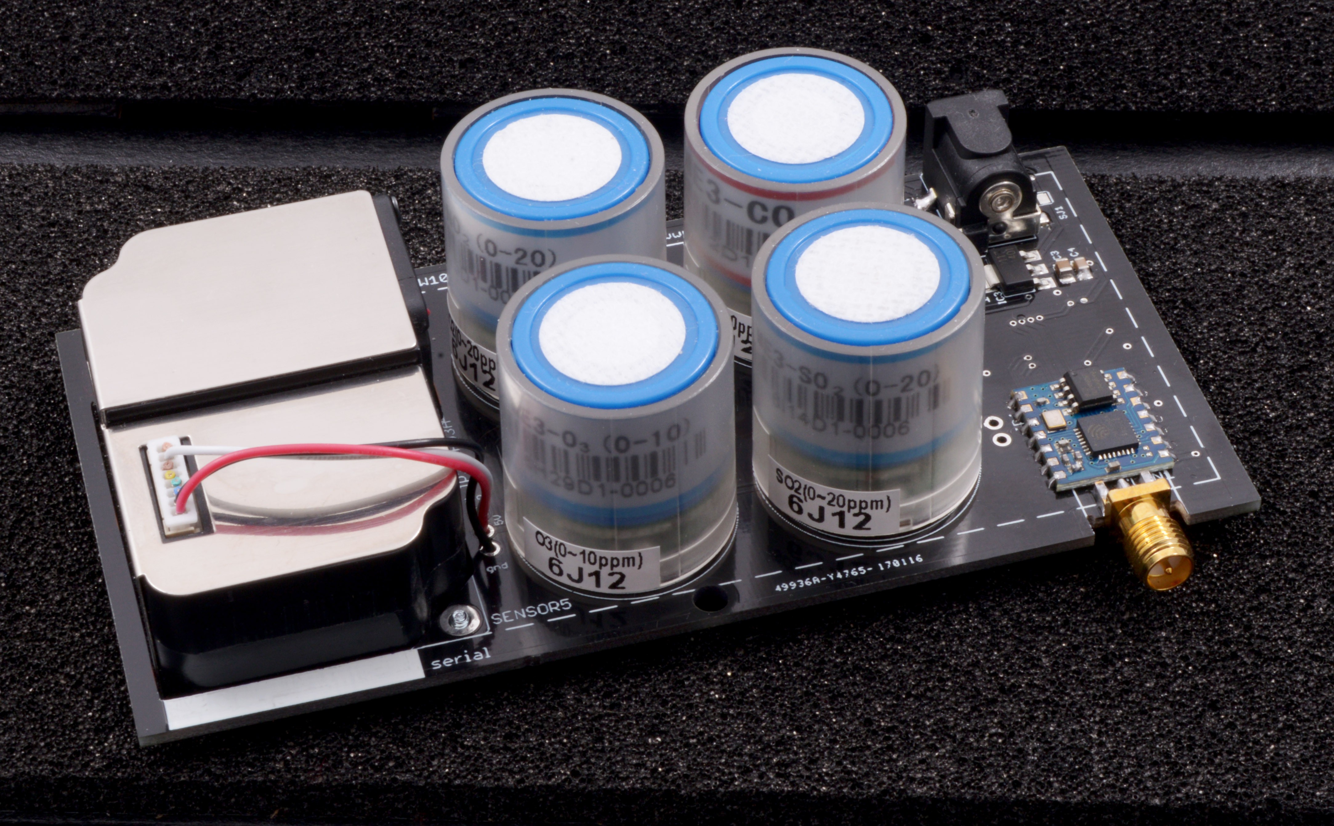
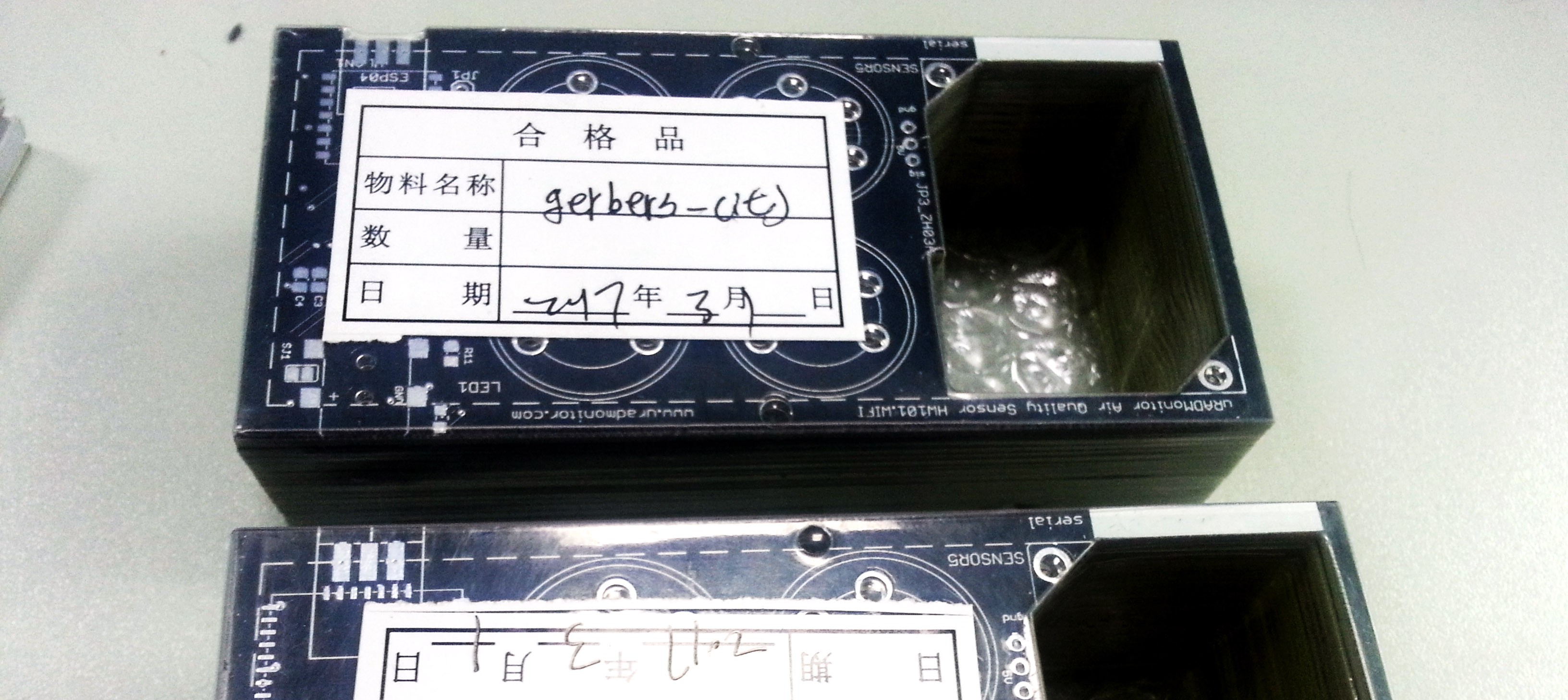
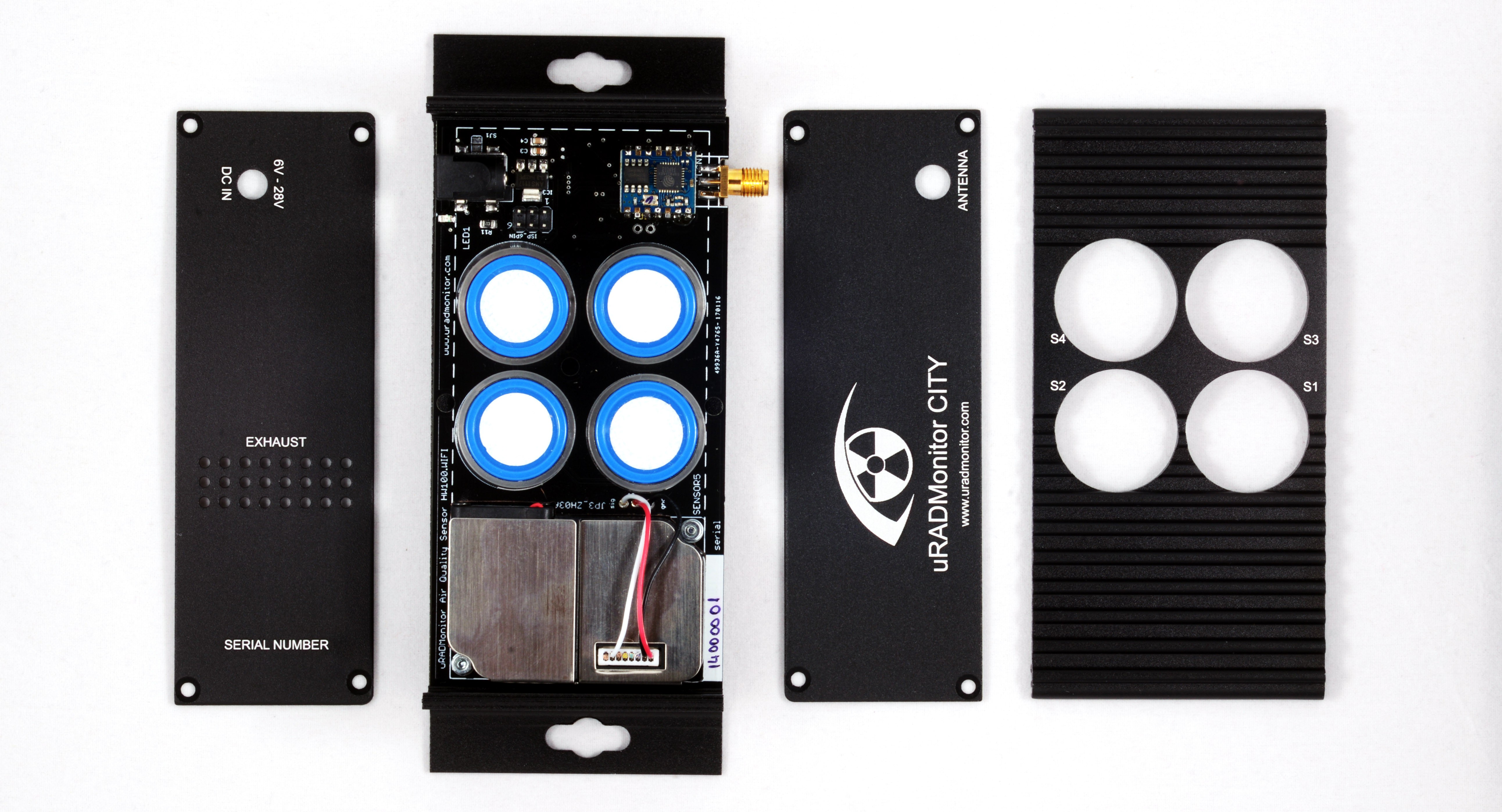
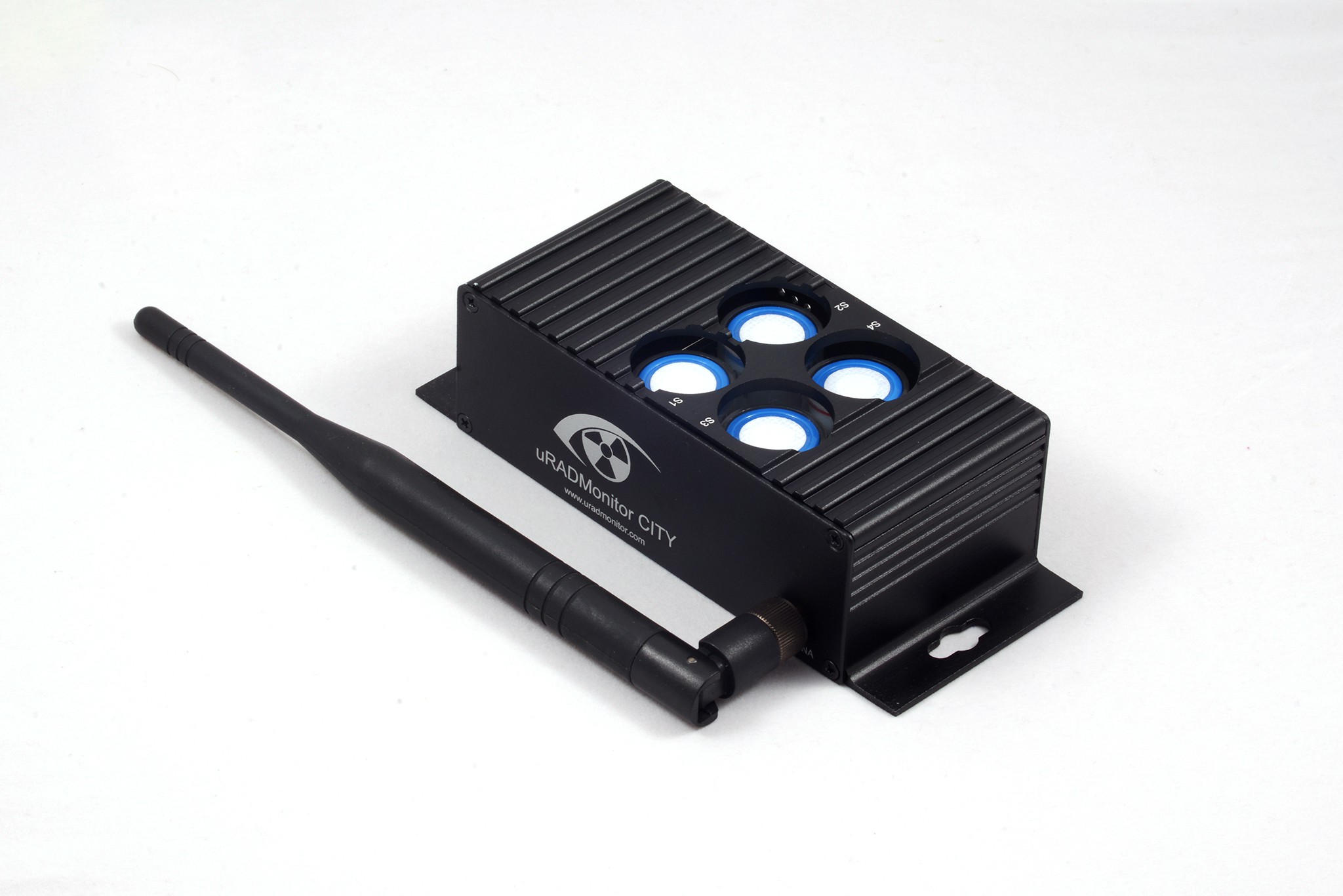
The first assembled PCBs were a beauty:

The sensors fitted the sockets perfectly. After spending a few hours trying to access sensor data, it became clear that unfortunately, the device didn't work. On each of the 4 electrochemical sensors, the voltage output was a constant value, no matter the fluctuations in test gases (SO2).
What happened was that I did a mistake when drawing the sensor footprint for the PCB design: the positions were mirrored, so the pins were all wrong. A stupid mistake that rendered the PCBs useless.


 Radu Motisan
Discussions
Become a Hackaday.io Member
Create an account to leave a comment. Already have an account? Log In.