 Tim Wilkinson
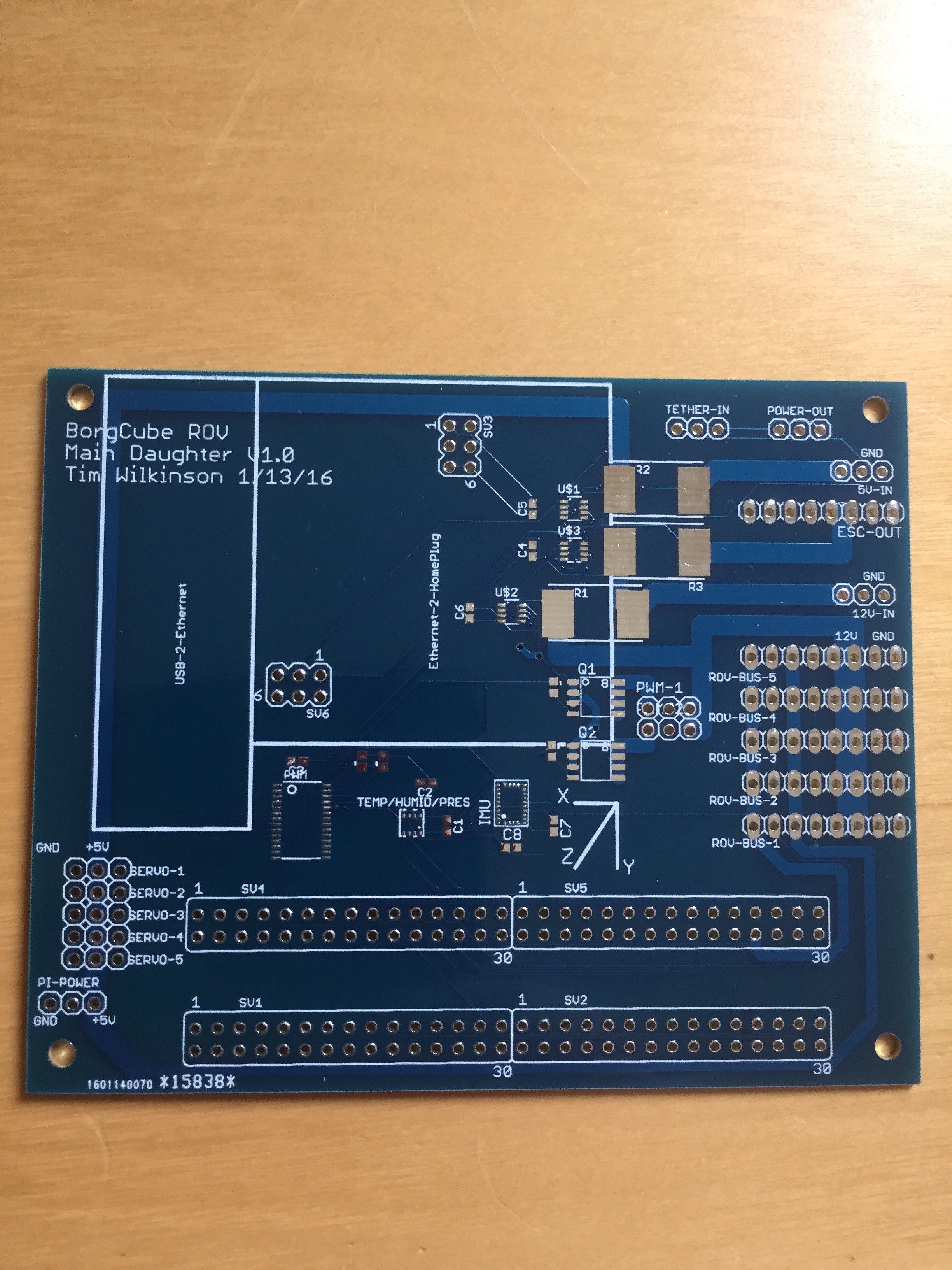
Received the main daughter board PCB yesterday:
And here it is populated:
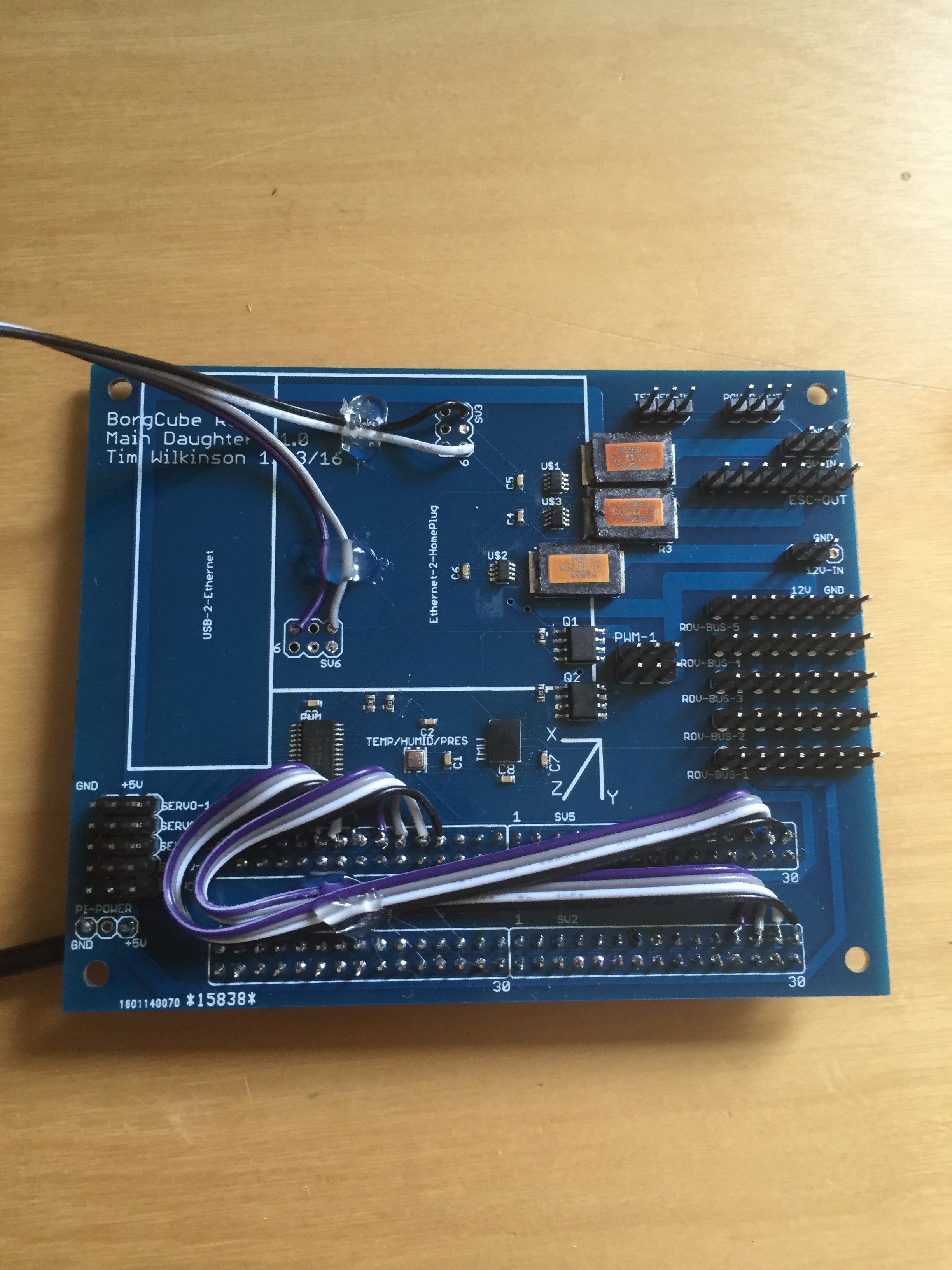
There were a couple of mistakes on the board (hence the wires you can see):
- I reversed the camera connections which link various edge-connector pins on the Pi. I cut the tracks and replaced with the ribbon cable you can see bottom/middle.
- The Tendra port didn't allow for the length of the ethernet plug. Once that's plugged in, the board will no longer fit in the 4" pressure vessel. I will rotate this 180 next time, but for now I'm connecting using the jumper cables you can see top/left.
Otherwise everything checks out, including all the power monitors, temperature/humidity/pressure sensor, IMU and PWM controller for the vision servos and lights.
Discussions
Become a Hackaday.io Member
Create an account to leave a comment. Already have an account? Log In.
Another minor issue - there should be thick copper tracks between the 'Tether-In' and 'Power-Out' connectors. This is the main path for the incoming tether power to be sent off-board to the UBEC. Not a major issue - I'll just have to solder the UBEC cables to the incoming tether directly.
Are you sure? yes | no