Alright, so the basic idea is to treat the (linear) audio-amp (TDA1510, so far..) like an op-amp, then to treat that op-amp as a comparator, then feed that comparator a PWM input. This [mis]treatment might be questionable, but it seems to work!
This log is a combination of a draft I didn't publish during the testing-process, and my most-recent results.
Previously:
Currently I'm driving my audio-amp with a 12V-on 0V-off PWM source (from another motor-driver). So, this means a lot of voltage-dividers. BUT: It also means that it's easy [easier?] to bias this input-voltage somewhere 'round half the supply-voltage (this is a single-supply amplifier).
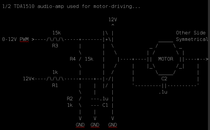
After TONS of experimenting: Here's a circuit that seems to work *great*:

The input is driven by a 0V=Off 12V=On source. Forward is handled by driving the 'left' input with PWM and the 'right' input with 12V. Reverse is... the reverse of that.
C2 is necessary due to oscillation. I can't quite wrap my head around this, but without it we get this: Well, shoot, I didn't take a photo...
          _____       _____
      12V|     |     |     |
In:    0V|     |_____|     |_____

    ~12V |     |     |     |
         |||||||     |||||||
Out: ~0V |     |_____|     |_____
Something like that, anyhow. I don't get it. But the capacitor (C2) *definitely* fixes that, in this case anyhow.R1 and R2 form a voltage divider biasing the inverting input of the 'comparator' at 1/2 Vsource = 6V. The capacitor, C1, just serves to try to filter out noise.
R3 and R4 values are large enough that we can (allegedly) pretend that they don't affect the output of R1 and R2... So, then, we have a voltage-divider which divides the input-voltage in half in each direction, WRT 6V. So, 0V at the input results in roughly 3V at the non-inverting input. 12V at the input results in roughly 9V at the non-inverting input. 3V is lower than the inverting-input's 6V, and we're treating the [poor] thing as a comparator, so the output hits the ground-rail. 9V is greater than 6V, so the output hits the V+ rail (as best it can).
Great! And confirms my theory that we can treat this audio-amp as an op-amp as a comparator...
(Note: In the interest of reducing part-count, I actually tie *both* "comparators'" inverting-inputs, and both circuits' 'R4' to the *same* voltage-divider (R1, R2, C1). In *this particular* circuit, it seems to work fine).
Note, *tons* of experimenting was done before coming to this circuit... Lots of "ideal op-amp" assumptions that just didn't seem to work-out... In fact, in some cases I'm almost certain I saw some large (milli-amps) current flowing between the inverting and non-inverting "inputs" despite their alleged 1Mohm input-impedance. So... again, I'm no analog-expert. The above circuit seems obvious... now.
Oh, important-note... don't allow the input voltage to *exceed* either of the power-rails. This was a kicker, I think... When the motor's on, the voltage to the amp's power pins was sagging nearly two volts. The input voltage, though, was still 0-12V. This, as I recall, resulted in some really odd behavior, like "latch-up" (?) where some PWM cycles would actually *stick* at the upper rail despite the input signal going low. Weird.
--------------------
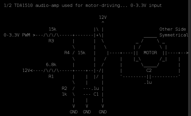
I didn't document them all, but here's another circuit... The idea being: the microcontroller I intend to use runs at 3.3V, so its output will be ~0V or ~3.3V. In the interest of using my current setup to test before actually building my end-circuit... The first step was to divide my current setup's 0-12V PWM output down to roughly 0-3.3V... That's simple with a voltage divider... I used the general-purpose assumption that as long as its resistors are at least 10x the output/load resistance, then we can "pretend" the output-resistance has no effect... So, the 0-12V PWM signal is fed into a 3.3k resistor, and that resistor is pulled to ground with a 1k. 'scoping the output of the voltage-divider looks alright, so I think the "pretending" was reasonable enough...
Now, again, we're [mis]treating this poor audio-amp as a comparator, so I figured why not bias its inverting-input at something like 3.3V/2=1.65V... Then use, basically, the same circuit as above...?

Looks alright, right...?
The result, as I recall, was basically an always-high output... at the upper-rail. Weird... no? I think this has something to do with the CMRR, which always seems to bite me in the a** whenever I do op-amp circuits.
So, no, it's not a comparator. Better to bias that thing somewhere 'round 1/2VCC and use small signals around there.
---------------
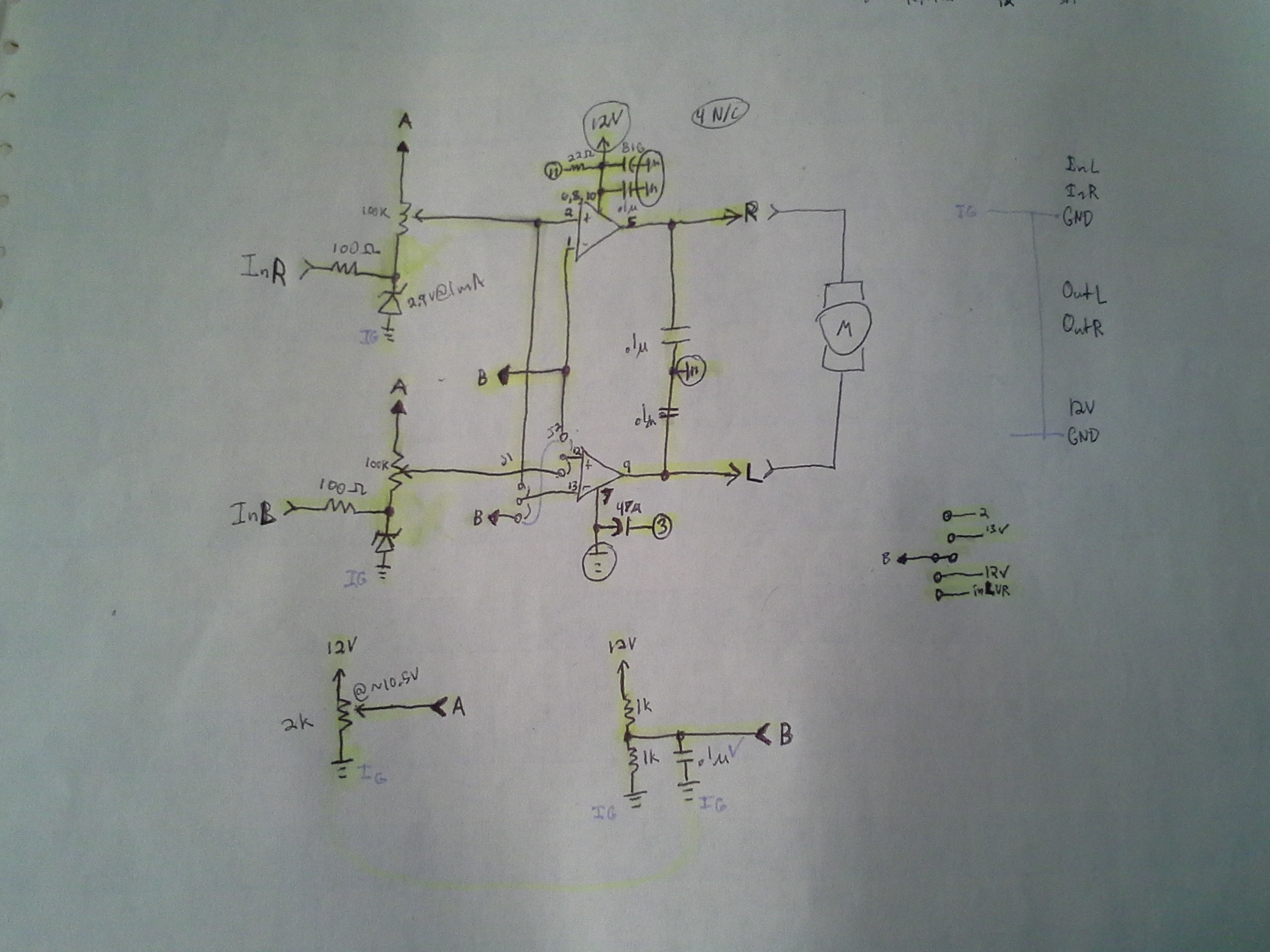
Here's the final (probably) microcontroller-output-friendly version of the circuit (which is now built on a PCB and has been tested with the 0-12V -> 0-3.3V voltage divider explained earlier).

A few things: The zener-diodes (and 100ohm resistors) prevent current from flowing *into* the microcontroller-output when the output is high. It may not be necessary (in fact, the PIC32 electrical-specs actually list the amount of current that can safely flow into the output when it's high... weird spec...? I'm almost certain I've never seen it on other uCs). My thought was that the 100k resistance between ~10.5V and the 3.3V microcontroller output would be similar to tying a load between two positive voltage regulators... they're not meant for regulation of negative-currents, so the lower-voltage regulator will rise to the higher-voltage. So, maybe, the microcontroller's output pins are similar...? Actually, *that* seems kinda absurd, now... but not so absurd is the plausibility that my microcontroller *might be running off a positive voltage regulator*. Also, the uC pins have protection-diodes, which probably would limit the voltage to something like 3.5V. Anyways, the zeners may not be necessary, but it made sense to me at the time. My original plan was to just use another resistor to ground, but then it occurred to me I might bump up the voltage on the motor-driver "amp", and then the voltage across that resistor would increase...
Also an interesting and beneficial discovery: The Zener Voltage is rated *at some expected current*... Check those I-V plots (and run experiments)! I've a ton of 3.9V Zener Diodes, and it turns out that at 1mA they're only 2.9V! That's a HUGE difference! And beneficial for my 3.3V circuitry.
Anyways, as far as the circuit's concerned, it's getting *roughly* 0V and 3V input to the bottom of that 100k potentiometer. I don't recall how, off-hand, but somehow I determined that 10.3V into a voltage-divider that had either 0V or 3.3V at its bottom terminal would give me an output-voltage slightly below or slightly above 1/2 V+ = 6V. (I wanted to bias the inverting input to 1/2VCC to limit the common-mode voltage, as well as to design this circuit closer to the one that will be used with my new audio-amps which *don't have an inverting input*). OK, so I need a 10.3V source, thus another voltage-divider.
End-Result: adjust the 2k pot to output something around 10.3V, then adjust the 100k pots while PWM is being input such that the output toggles above and below 6V.
Seems to work great. Surprising, kinda, judging by how much difficulty I had getting the thing working at all in the first place... now it seems almost like an ideal op-amp or even comparator circuit.
The jumpers allow for Locked-Antiphase or DIR/PWM input. My current setup drives one output high and PWMs the other, then swaps those for the other direction. But the new audio-amp uses only *one* input for *both* its outputs (one is inverted). So that will require locked-antiphase (where 50% PWM results in no motion). So those jumpers allowed me to test that before I had the new chips.
Alright, enough talk...
First: DEFINITELY put a heatsink on it. A good one. I might've gone overboard, but it doesn't even get hand-warm now, and before it was so hot I could smell it and dropped-out (due to the thermal-protection circuitry?) quite a bit. (TODO: This might be the problem with the Class-D amp... maybe that heatsink was too small...?)
Here's the end-product *almost* complete:
And here is a screenshot from the not-yet-editted video of the system functioning:

NOTE: So far "freewheeling"/"flyback" diodes *HAVE* been deemed necessary... They're not shown in the schematic but have been attached off-board via the terminal-block.
My original thought was that since the outputs of a linear amp are push-pull, the amp *might* be capable of *preventing* freewheeling voltage-spikes.
This logic... plausible, still, I think. But *most likely* would require feedback, treating the amplifier as an op-amp rather than as a comparator. Worth exploring, but might have some other consequences... The biasing would have to be *just right*, and I think the gain would have to, as well. The actual output might have to be reduced such that it doesn't *quite* reach the rails...? I'm not sure. If that's all the case, then four diodes per motor is minimal in comparison...
As it stands, this is darn-near, if not fully-functional as a motor-driver. It's a few extra components, but not bad. A bit of calibration may be necessary when using a different supply-voltage (could that be avoided?) Definitely warmer than, say, the LMD18200 I've used for some time, but a heatsink seems to handle that fine. Switching-speeds...? I think I'm running something like 31kHz, right now (way above audible range) and it seems to be handling it fine.
------------------
Coming up next....
Video!
And Later....

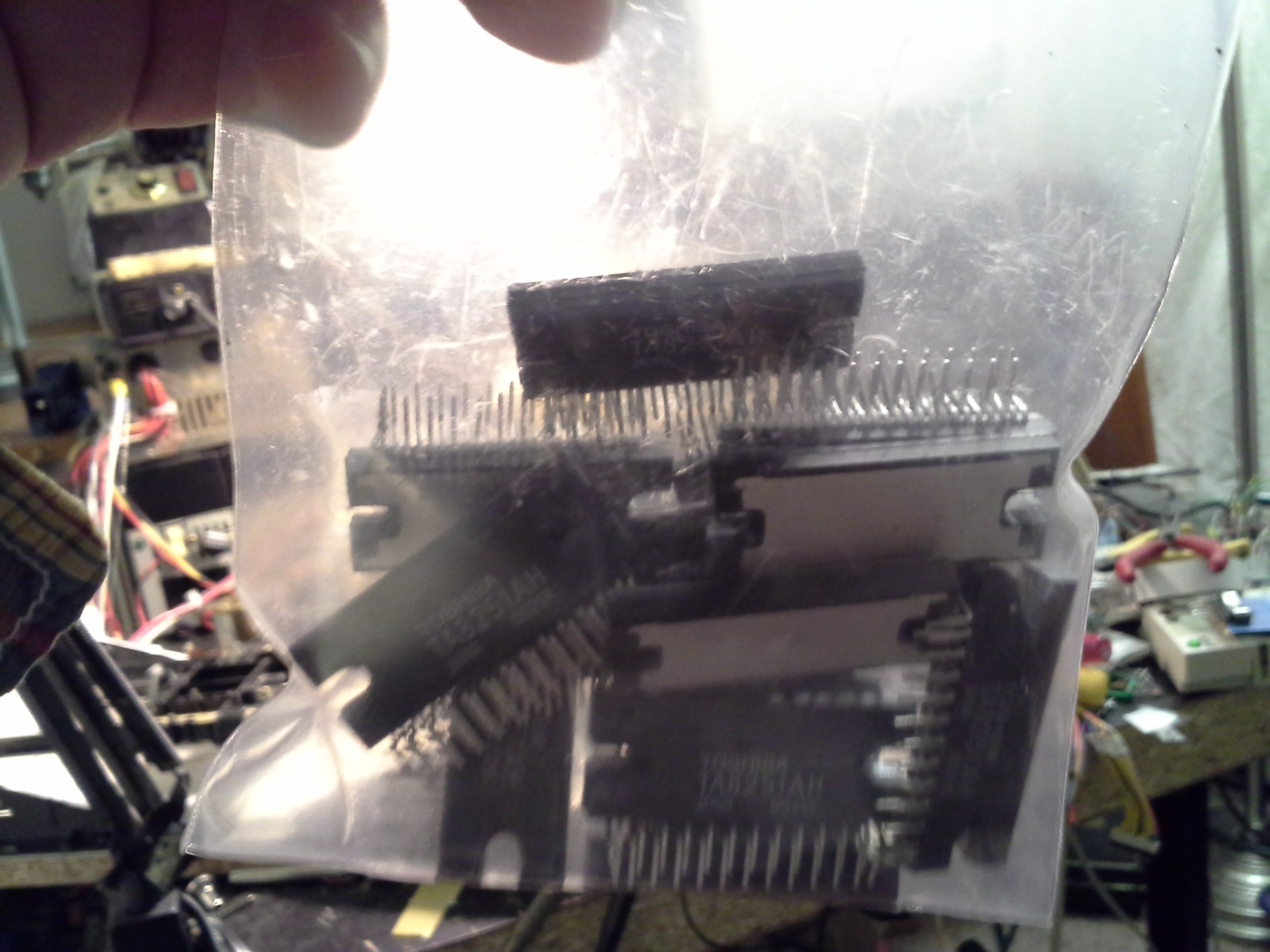
Each of these audio-amp chips could plausibly control *4* DC motors, or two bipolar steppers! With sale-prices I got this entire bag for $5! Or one could look at it as though I placed an order for much-needed rotary-tool bits and got drivers for 56 motors for $2 :)
 Eric Hertz
Discussions
Become a Hackaday.io Member
Create an account to leave a comment. Already have an account? Log In.