 Stefan Lochbrunner
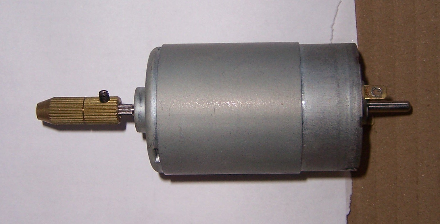
Thought about using a rotary tool but I'm not sure if the machine will be able to handle it. For now the plan is to use a DC motor with one of those cheap self-tightening chucks (although that's not too different from a regular rotary tool):
Update 2015-11-24:
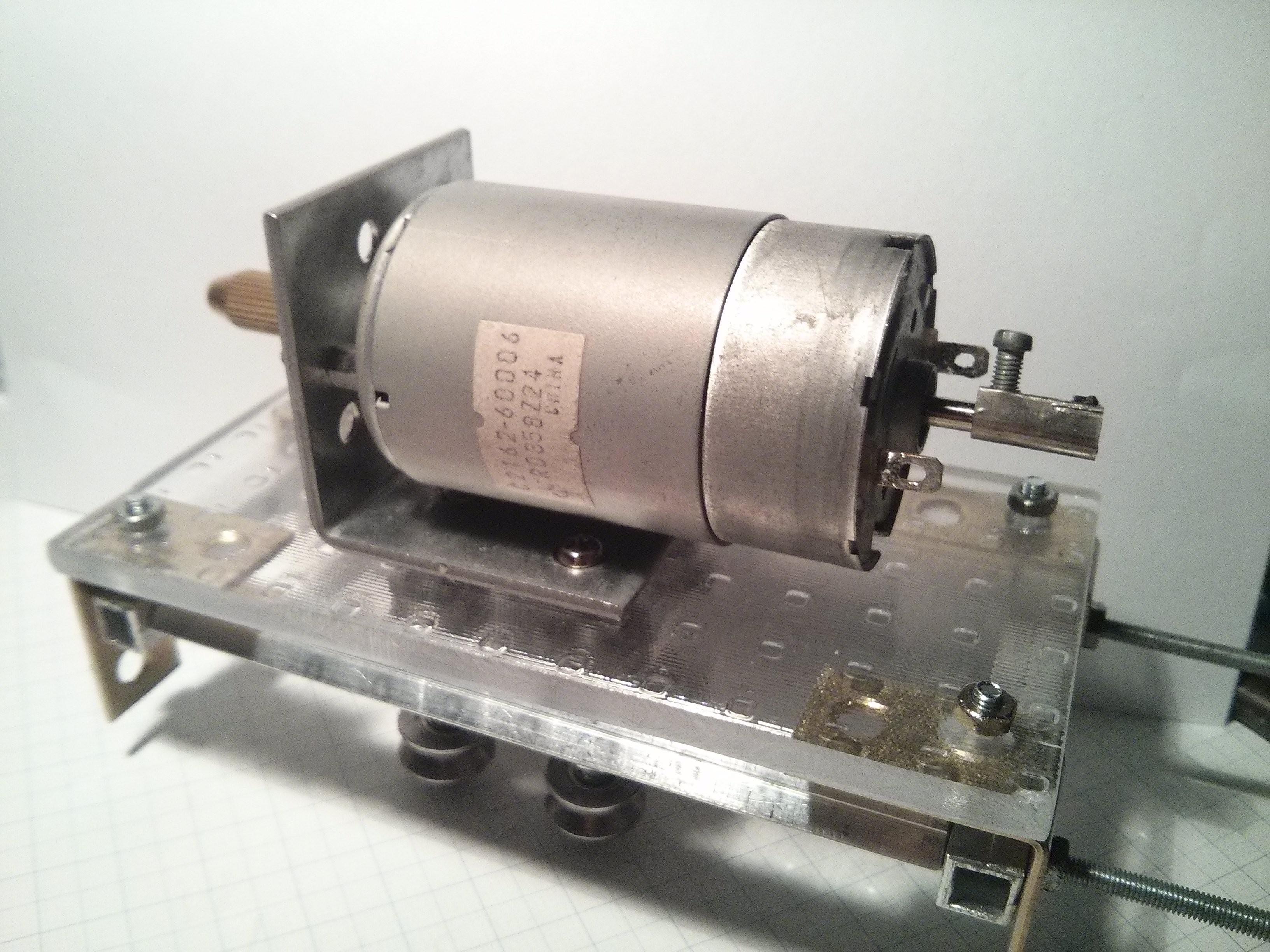
Some thoughts on how I'm going to mount it: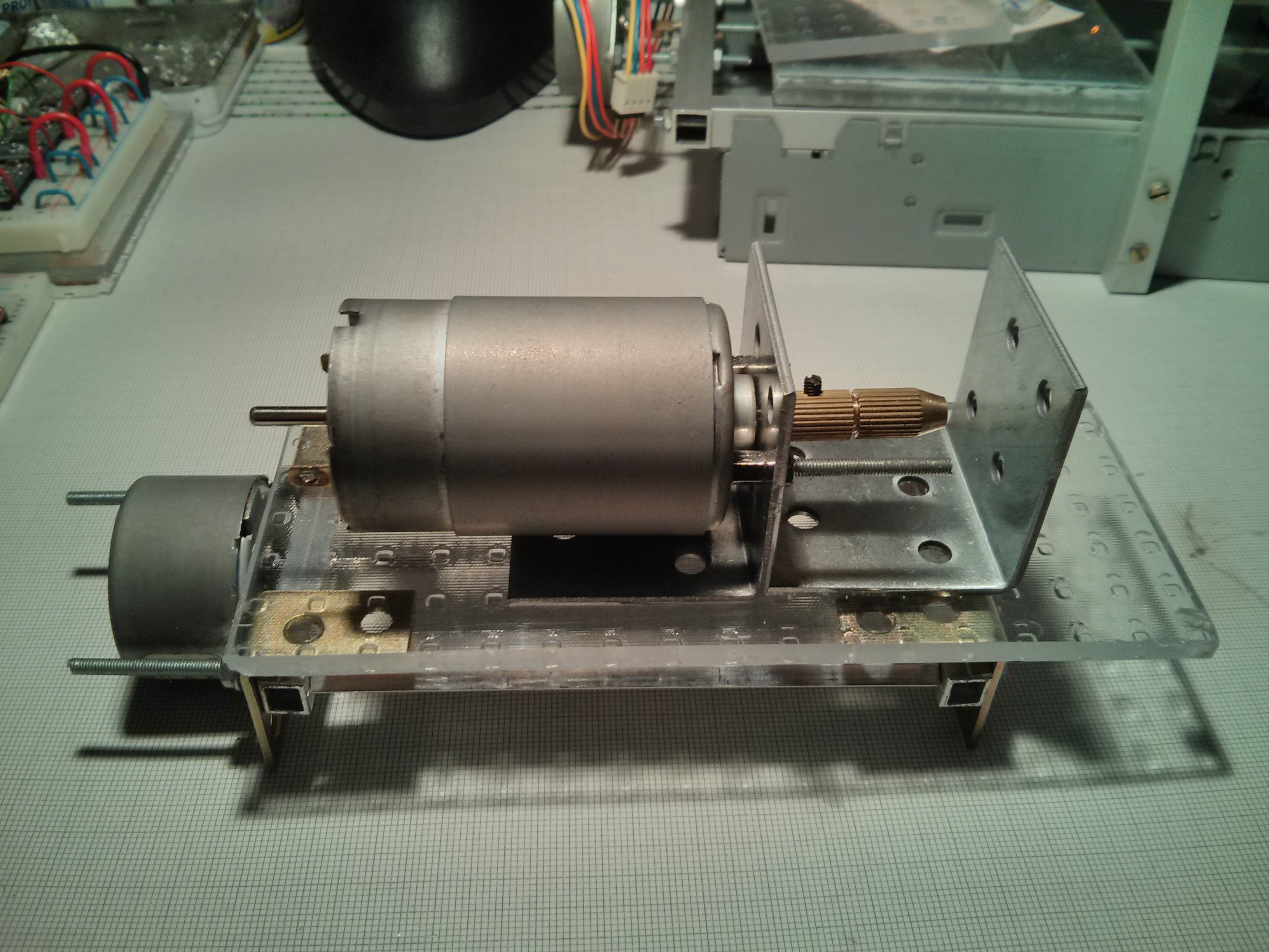
The motor is attached to an angle and will also be supported further on the left. Probably with some metal or acrylic pieces and a hose clamp to pull it tight against the base plate. The 2nd angle on the right will be a support/guide for the bit. I don't have any 1/8" inner diameter bearings (or drill bits for that matter) that could act as low friction guide so I guess a hole will have to do; it remains to be seen how I'm going to make that hole.
Update 2015-12-23:
I'm still waiting for the v-groove bearings and since I'd like to fabricate most of the next batch of parts in one go I haven't gotten too much done on this building wise. However, I did some tests on reducing wobbling of the bit. Initially the bit was off by about .5mm such that the very tip would move in a circle with a diameter of 1mm. I tried reducing it with a makeshift bushing but this had too much friction, causing the motor to slow down or even stall.
Pushing on the chuck such that the tip of the bit would go towards the center approximately halved the wobble and by rotating the bit inside the the chuck got it to a point where the wobble is negligible. The problem is that this chuck holds the bit only on a slim ring where its jaws close and the end of the bit that is inside the chuck has some space to move around. In hindsight this is pretty obvious but I just couldn't resist when I saw this chuck on eBay. I guess this will have to do in order to finally get the machine running for the first time and I'll make some improvements once I'm there.
Update 2016-03-03:
As I mentioned in the other log I had to reorder the bearings but now that the second order arrived I finally got back the motivation to continue work on this.
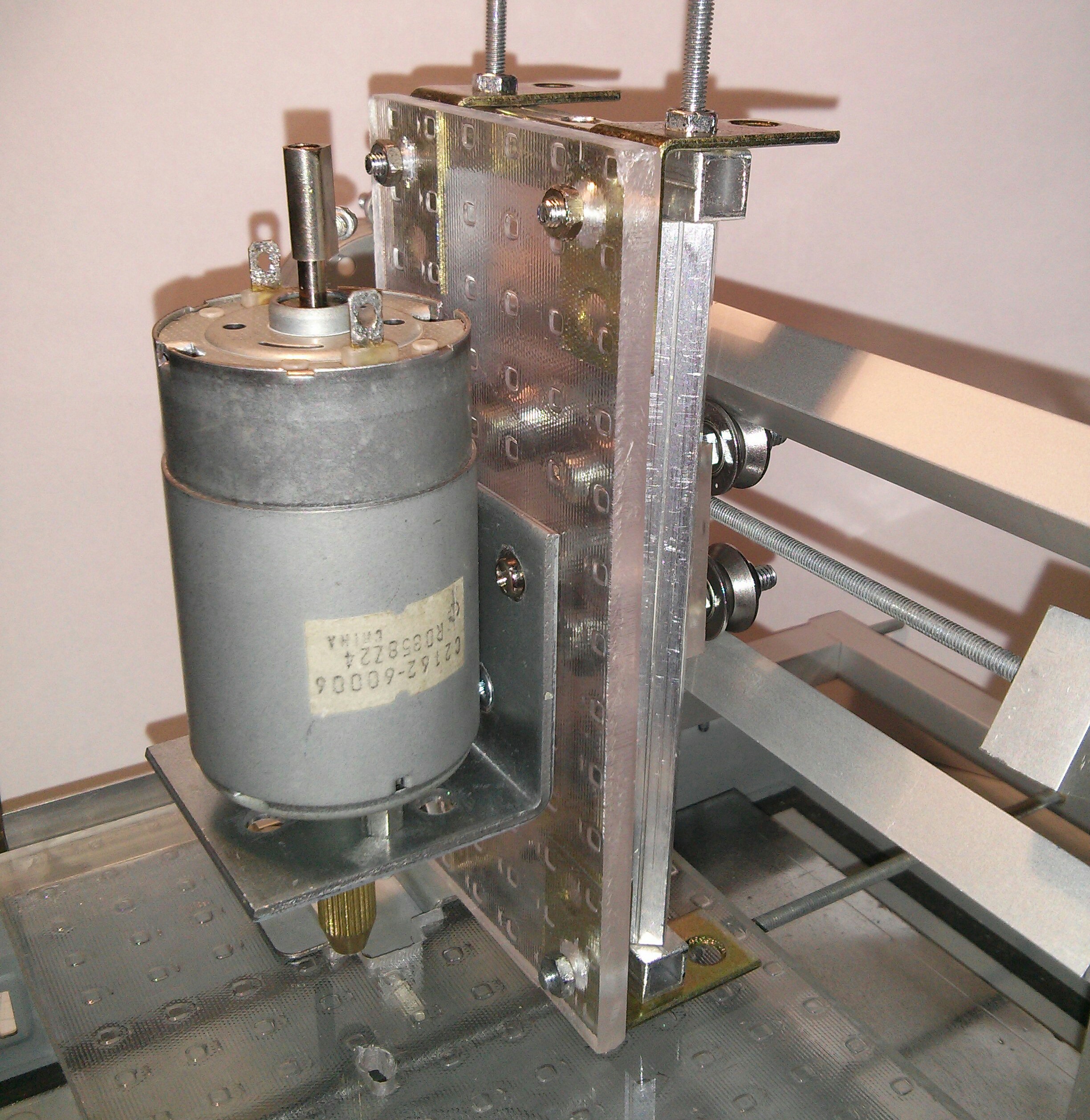
I pretty much just implemented the ideas outlined above so this is how the spindle mount looks like now:
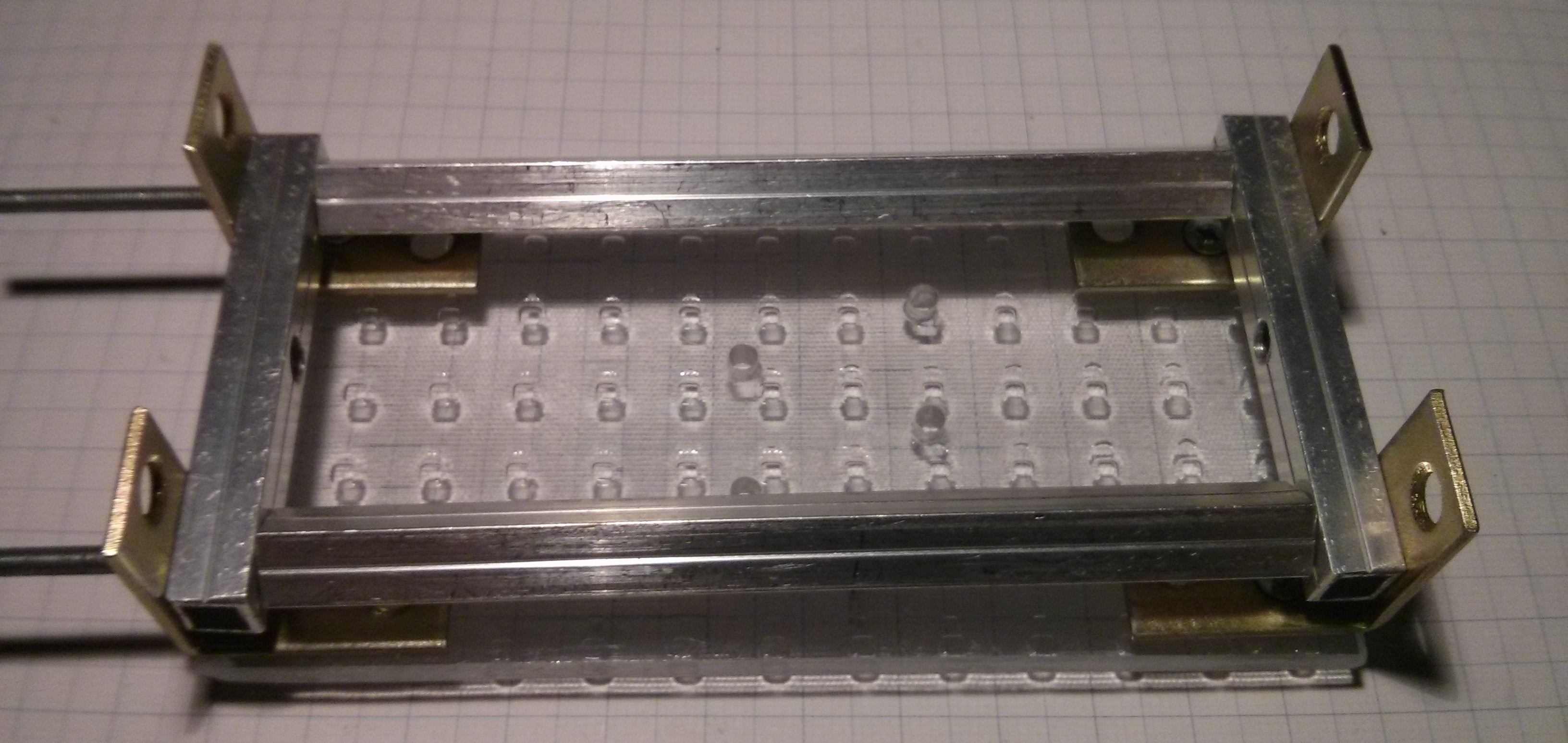
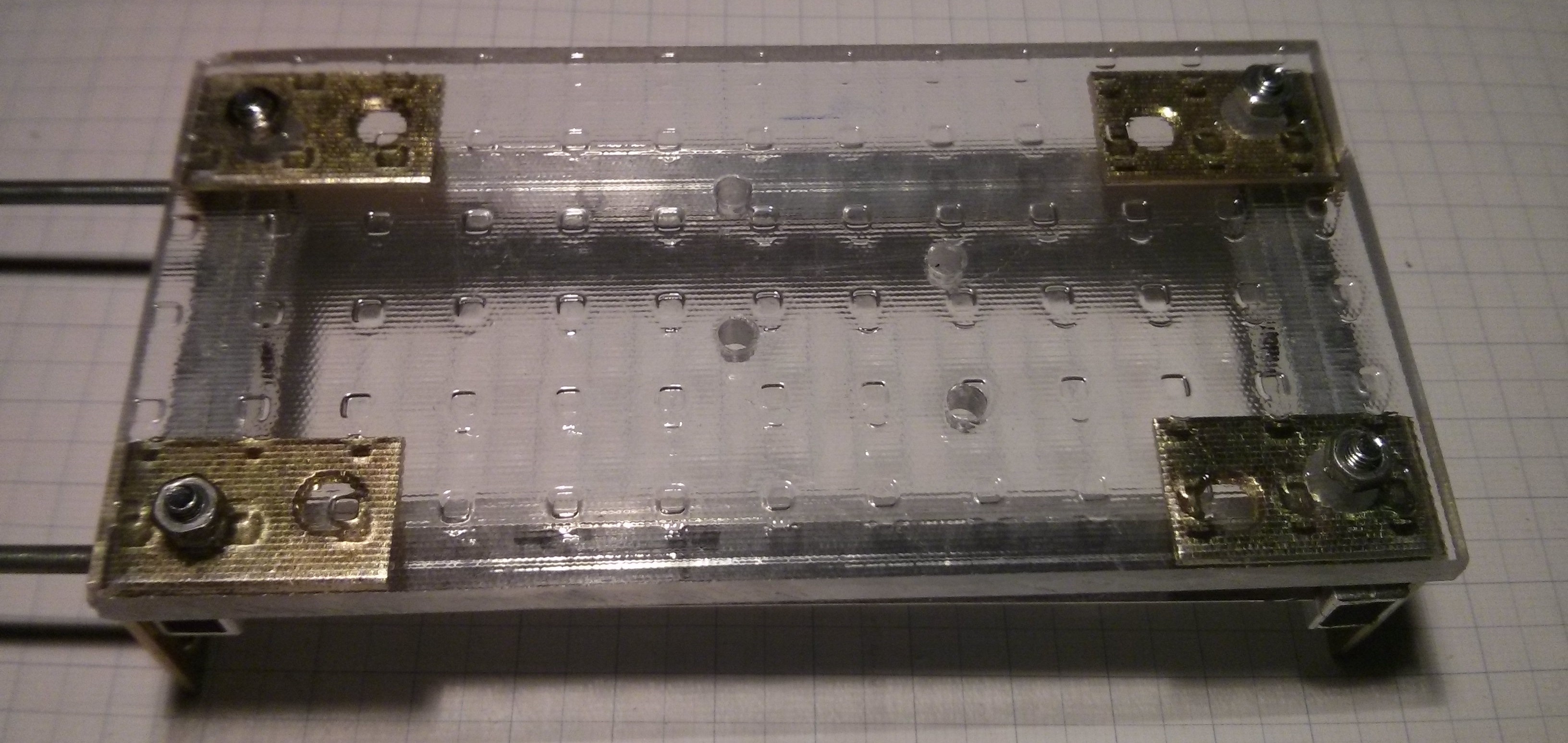
I made some mistakes on the acrylic base plate since I rushed it a bit to get it done and see if this concept would work but those are primarily cosmetic so I could just make a new plate if I feel like it. I also still have to shorten the brass right angle pieces since they limit the machines range of motion a bit. Assembly of the spindle-mount/z-axis (shown below) was a bit of a pain because a couple of screws are obstructed - the ones under the motor on the metal angle, for example - but once done it seemed to work quite well. The optical flaws aside, the motor is mounted pretty sturdily to the z-axis so if I can get rid of the wobble of the bit it should work nicely.
Discussions
Become a Hackaday.io Member
Create an account to leave a comment. Already have an account? Log In.
Lookin' Good!
Are you sure? yes | no
Thanks! I just hope it's going to mill just as good as it looks :P
Are you sure? yes | no
Looks like you're well on your way to finding out soon :)
Are you sure? yes | no
Gah! Chuck-wobble revisited :/
Are you sure? yes | no
Getting some ideas from your mounting-plate. Thanks :)
Hey, FYI, if you've got some old hard-disks laying 'round, you might be able to score an 1/8in inner-diameter bearing from the voice-coil mechanism!
Are you sure? yes | no
I do have a bunch of old HDDs, thanks for the tip! :)
Are you sure? yes | no
I've only taken apart two so far and only got 5mm-ish ones. On this note though; I got a bunch of 3mm-ish ones from old PC fans, not quite sure if they are 3mm or 1/8in but they don't fit around the bit. I guess I keep looking.
Note to self: Get better calipers. Which means cheap ones from eBay... yes, those would be an upgrade :(
Are you sure? yes | no