Close
0%
0%

Arduino Grow Chamber

Automating feeding and watering of secluded plants via WiFi in a pseudo-IoT system

Similar projects worth following
The problem:

My location allows me to grow a few marijuana plants (I use it medically, but recreationally it's also legal). I have a 'grow chamber' set up already, but since I'm not that good at scheduling watering/feeding and lighting, I wanted to automate as many of the items as I could.

The goal:
Using an Arduino UNO and some clever coding, I should be able to make a four channel feeding system that automatically monitors the moisture of the soil and waters appropriately. A tiny bit more code would allow the lights to also be controlled by the same system. Ideally all that would need to happen after that is every few days checking the water tank level and plant condition.

The same system would be usable for other plants, particularly indoor grown vegetables.

Settings would originally be configured using an SD card in the data logger, and would include SSID/passkey for WiFi, number of active sensors, moisture thresholds for each sensor and lighting schedule. WiFi would initially be used to contact a local NTP server to get the local time for data logging. Logging would be general status information (i.e. Lights turning on/off, watering cycle)

Potential future upgrades would include:

~ Sensor to monitor water tank level

~ Web interface to show current moisture status and recent events (making this more of an IoT system)

~ SMS/E-mail/Andorid push notifications of errors and alerts

~ Adding serial camera capabilities to take IR/UV photos (If we get this far, would probably have to upgrade to an Arduino Mega)

Details of parts list: http://pastebin.com/5V81YMuK

Original Inspiration: http://arduinosensors.com/index.php/soil-moisture-sensor-interface-with-arduino-uno/

Arduino_Grow_Chamber_Baseline.ino

Baseline testing sketch for water sensors

text/x-arduino - 491.00 bytes - 12/24/2015 at 23:00

Download

  • 1 × Arduino UNO R3 Core System
  • 1 × Sensor Shield for UNO Core System
  • 1 × XD204 Data Logger Shield for UNO Core System
  • 1 × ESP8266 WiFi Transceiver Module Core System
  • 1 × Molex 71973 style 2x4 female header Core System - Allows WiFi to be mounted vertically for better signal

View all 22 components

  • Baseline testing has begun!

    Heather-Lynne Van Wilde12/24/2015 at 23:03 0 comments

    Took some work (and a chance to sleep on it) but I cobbled together a tiny sketch to get initial calibration data on the sensors that I'll be using. Still fine tuning the data, but for the dirt that I borrowed from the front flower beds, I'll want to keep the value somewhere around 100. Updated information in the instructions!

  • ESP is mounted!

    Heather-Lynne Van Wilde12/24/2015 at 07:04 0 comments

    I got the rest of the wires I was hoping for, and the patience needed to do the detailed soldering (multiple pins when you have shaky hands isn't always fun), but I'm now ready to start wiring up the sensors and test programming!

    This was theoretically the most physically difficult part of the build for me, now it's going to be a lot of coding work. Stay Tuned! =^_^=

  • Parts have arrived!

    Heather-Lynne Van Wilde12/21/2015 at 08:39 0 comments

    I finally got the last of the parts I needed a few days ago. Ironically, it was about the most important part, the SD card reader/RTC board. Ironically I'm not going to go too far too fast at this point of development because of two tiny problems:

    • My partner took all the computer mice with her on vacation, and I'm too lazy to move the wireless keyboard and mouse to my programming computer across the room. That's okay, she has a warrantee replacement wireless one coming anytime that I'll conscript on her =P
    • When I ordered the DuPont lead connectors, I didn't count on how much of a pain it is to crimp them for prototyping. I can do it, but it looks incredibly dirty. A set of male-female breadboard jumper wires will actually do wonderfully for it, and the set I got off of Amazon should arrive on the 24th and comes with a mini breadboard! Yay for streamlining power and ground rails for the moisture sensors

    So far, everything with status lights does power up, but I haven't been able to start testing serial commands to make sure that that's all working properly. Hopefully soon I'll make progress there though.

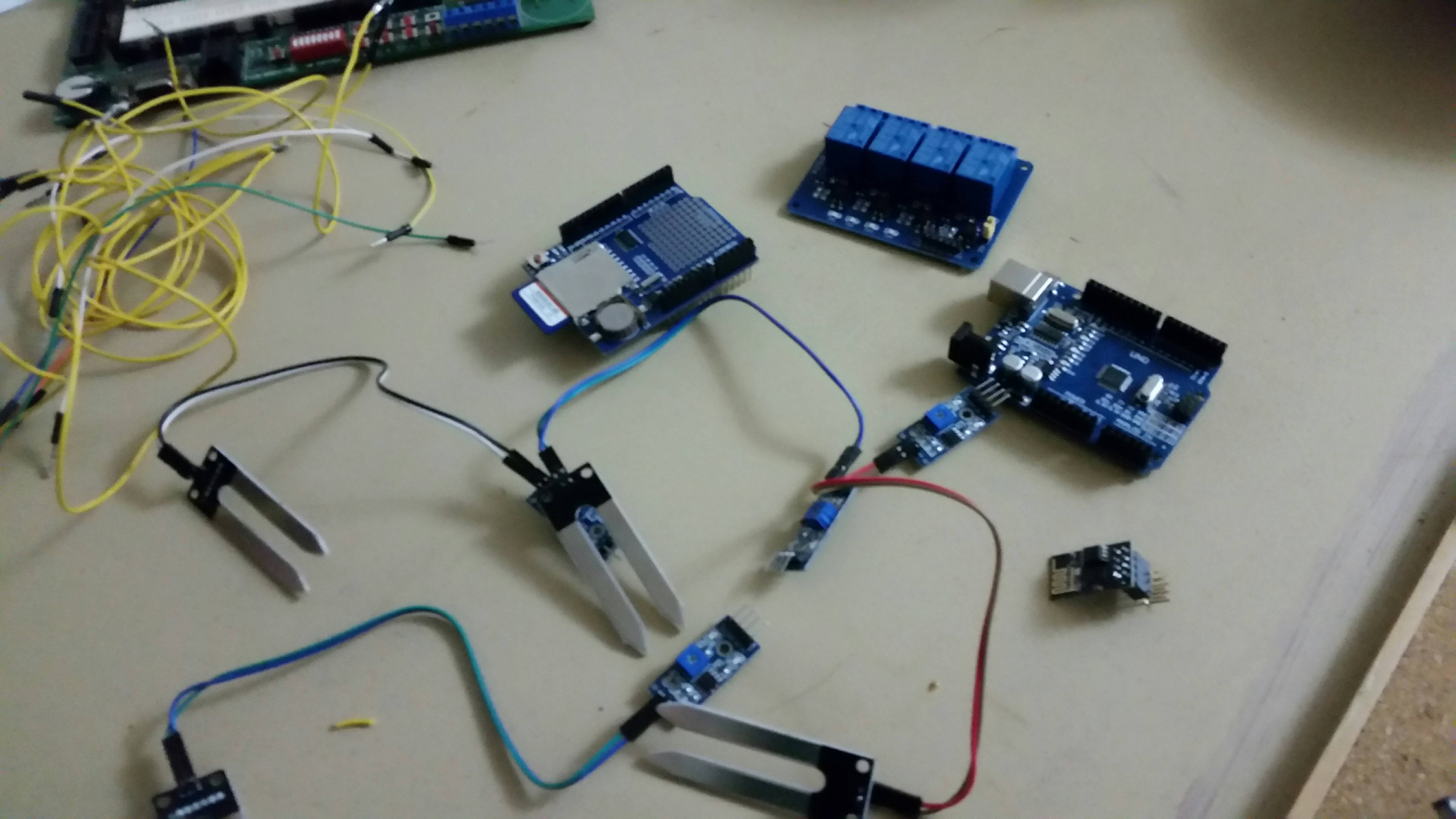
    All of the boards and parts (that rats nest in the corner is my jury-rig of the wires connecting the moisture sensors to power, ground and their analog inputs)

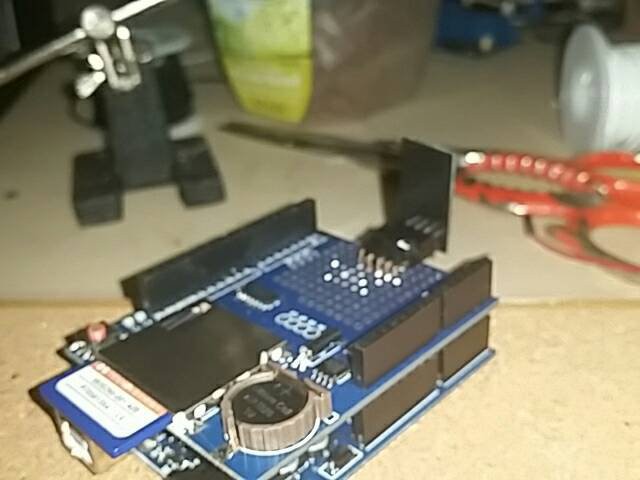
    From top, clockwise: 4 channel relay board, generic R3 UNO, an ESP-8266 sitting in a right angle connector, and the SD card/RTC shield. The 128 MB card that's currently in it is going to be insane overkill for a lot of the development cycle of this system.

  • And they're off!

    Heather-Lynne Van Wilde11/20/2015 at 23:27 0 comments

    All the parts are shipped now ... should have everything anywhere from Dec 8th and ... Jan 12th ... gonna be a long holiday =P

  • The Journey Begins

    Heather-Lynne Van Wilde11/19/2015 at 11:02 0 comments

    Had a chance to start getting supplies to begin the prototyping and basic code work. Everything won't get here until late December - mid January, and it's not all the parts, but it's enough to start learning the Arduino IDE and creating all the software. Only totaled out to about $30, and with a couple of wire swaps depending on configuration, I can test up to four soil sensors, and the LEDs on the relay board will simulate the solenoids and light connection. Got everything off of eBay China, and here's the list of what I got:

    Once I have the moisture sensor software itself working, I can easily drop the sensor count to 3 and use the extra relay channel to test the power connections.

    Now comes the hard part: waiting for all the bits and pieces to arrive!

View all 5 project logs

  • 1
    Step 1

    Building the Core System

  • 2
    Step 2

    Prepare the right angle DuPont connector to be able to accept the ESP8266-01. The way I did it might be considered a bit dirty, but since it's a first prototype it did what I wanted it to do.

    • The first thing I did was actually remove pin 5 from the connector. Since the pin wasn't used in this configuration and all the pins surrounding it were common power pins, it made things easier for me to solder if the pin was just gone.

    The right angle connector with the pin removed. I used the protoboard afterwards to make sure any bent pins were put back in place before I started soldering.

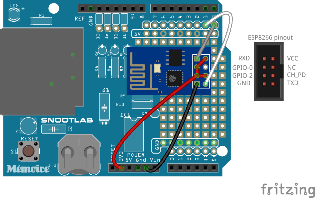
    Wiring diagram and pinout of the ESP8266-01, to help follow along

    • Next, I wired the 3.3V, GPIO-0, GPIO-2 and CH_PD lines together. The 3.3V line is obviously the power input, and the other pins we want to keep artificially high at all times (GPIO-0 updates firmware when the signal is LOW, GPIO-2 has to be high or the chip won't boot, and CH_PD is a power save function; low it goes into standby, and high it's fully operational). For me, I wrapped a stripped piece of wire around the four pins (so much easier with that other pin removed!), soldered it shut and then wrapped it in electrical tape to make sure none of the other pins came in contact. At this point, I started doing continuity tests at each stage of my work to make sure nothing was shorted together that wasn't supposed to be.

    Definitely would not do this on a production model!

    • Solder the connector onto the board. I'd place the ESP chip in the holder just to make sure you have the right clearance. On my board, I used the 3rd and 4th row of the proto-board.
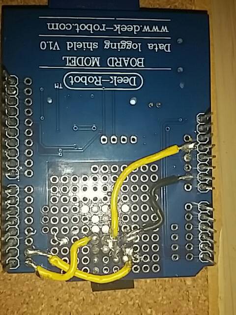
    • At this point, it's basically connecting the wires in place. Any of the jumpered pins gets sent to the 3V3 power pin, Ground to Ground, RXD to DIG_0 on the Arduino, and TXT to DIG_1 on the Arduino (D0 and D1 are the Arduino's TX and RX, respectively. Remember, the Arduino TX's to the ESP's RX, and the Arduino RX's info from the ESP's TX!)

    I know, wire color coordination complete fail! I didn't find the other color I was looking for for the data lines until after I'd finished wiring all of them. The top yellow wire is the 3V3 line, so even though it looks dirty it's not that important because I have my choice of four pins to connect to. Black is ground and the other two are the TX and RX pins.

    • One last test to make sure nothing got cross wired (bad solder connections, especially at the 3V3 connection will make the chip go 'poof' very quickly!) and then covered the connections with a layer of electrical tape, and we're done!

    A little electrical tape goes a long way to keep stuff from blowing up!

    Hacktip: If you don't have a multimeter handy (like I did, whoopsie!) here's a quick and dirty continuity tester I made out of some of the other components I was using

  • 3
    Step 3

    Learn your sensor's baseline

    Since it seems that different types of moisture sensors have different outputs, not to mention different soil types and plants require different amounts of water, it's a good time to figure out what a nominal value would be for your particular sensor. A quick hook up of a sensor and a tiny sketch for the Arduino will give you a real time measurement so you can play with the dirt and get the right values.

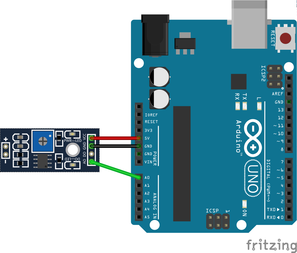
    Here's all you really need for this part. I'm doing it on the shield, just because I want to get used to having the other parts to worry about.

    /*
      # Baseline code for moisture sensor
      # Editor            : Heather-Lynne Van Wilde
      # Date              : 24.12.2015
      # Version           : 1.0
      # Original Source   : http://www.dfrobot.com/wiki/index.php?title=Moisture_Sensor_(SKU:SEN0114)
      # Connect the sensor to the A0(Analog 0) pin on the Arduino board
    */
     
    void setup(){
       
      Serial.begin(9600);
       
    }
     
    void loop(){
       
      Serial.print("Moisture Sensor Value:");
      Serial.println(analogRead(A0));  
      delay(1000);
       
    }
    Full disclosure: The code is indeed copied from DFRobot's wiki, but with a few changes
    • Their moisture levels didn't correlate with my sensor (on theirs, the wetter the soil, the higher the value, on mine it was the opposite. Bone dry dirt was about 1100, almost good soil about 90)
    • The baud rate was -way- too fast for my Arduino to read. I have a clone with a non-FTDI chip, and the 56K they called for was both unneccesary and caused errors in avrdude. I did confirm with my parther's genuine UNO that the faster speed does work though.
    • I massively slowed the delay. I didn't need a dozen reads a second. It's dirt, not a radio signal after all.

View all 4 instructions

Enjoy this project?

Share

Discussions

Similar Projects

Does this project spark your interest?

Become a member to follow this project and never miss any updates