I have made lots of MCU based circuit and gadget, but felt some missing piece of knowledge between logic circuit (TTL) and software programmable circuit, so CPU.
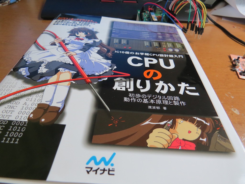
This time I found a very nice Japanese book, denoting "how to make CPU by TTL"
Its ISBN is ISBN4-8399-0986-5, and can be found in amazon.co.jp. or amazon.com
This book has a lot of catchy "Anime illustration" but I guess it must be one of best to understand and make a missing piece between wired simple logic to software programmable logic.
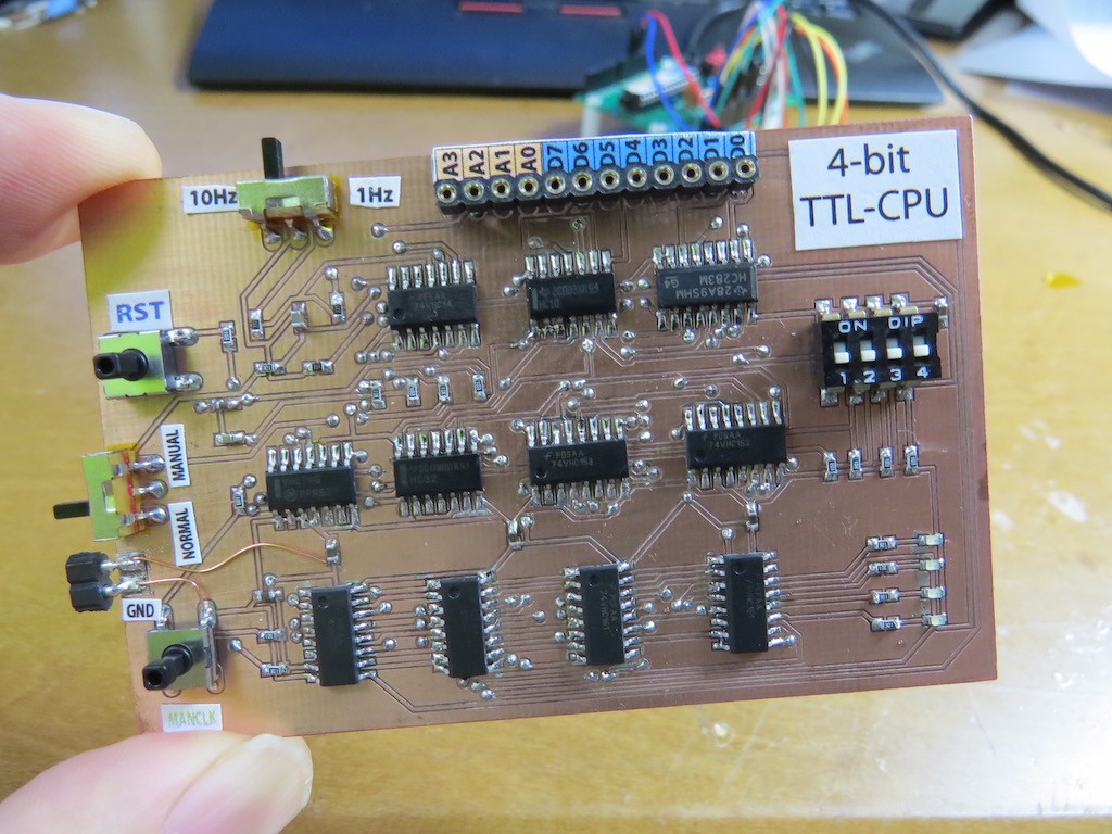
I quickly made its circuit by TSOP components. It has 4-bit I/O and input port is connected to DIP switch, and output port is connected to LEDs. Clock speed switchable by 10Hz or 1Hz (not MHz, nor GHz, just to make sure ;-), or manual clock, which enables its operation "step-by-step".
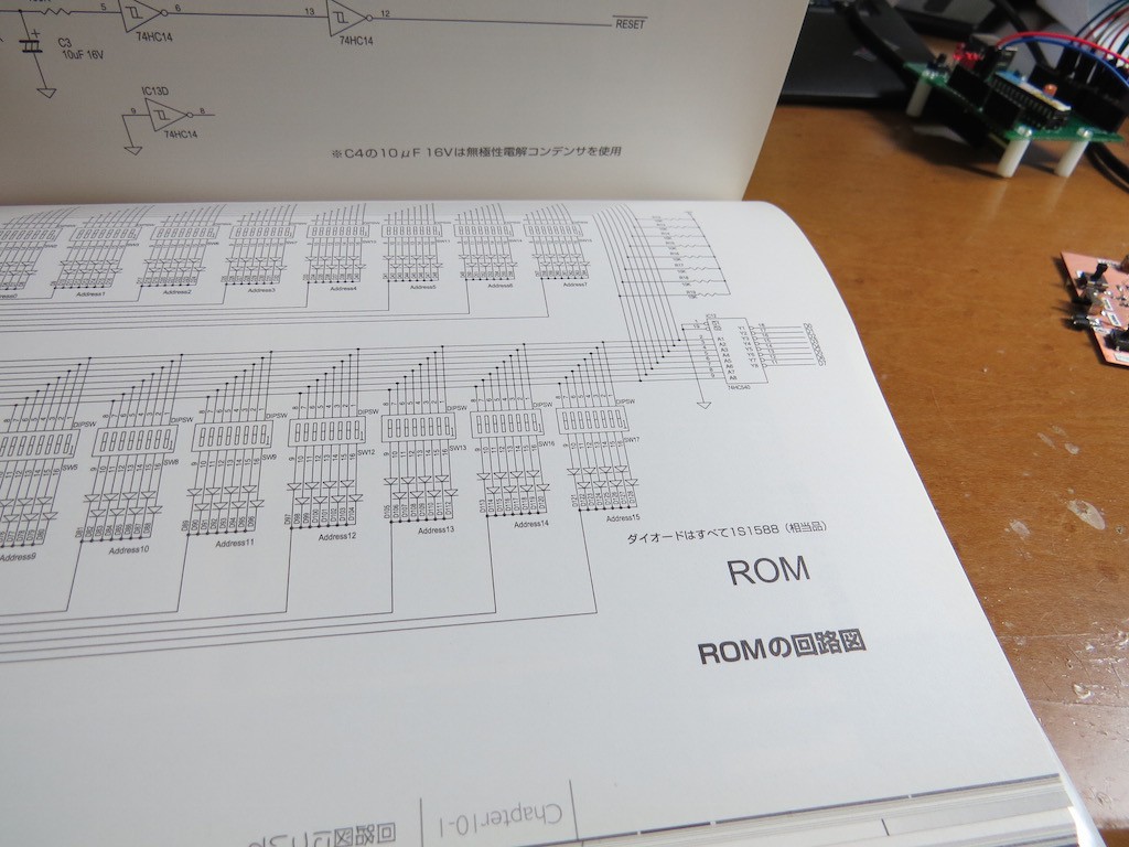
In this book, ROM, where program is stored, is made of bunch of DIP switch and diodes. Basically I don't want to make simple-complex circuit, some "switch and diode paradise" and I avoided to make it and...
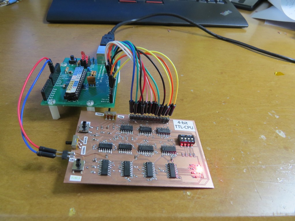
ROM is emulated by Arduino. Something funny to see 8-bit MCU is working as a ROM of 4-bit CPU :-)
This CPU is well designed, even though just 11 TTLs, it supports the command below,
MOV A, Im; MOVE lm to A register
MOV B, Im; MOVE Im to B register
MOV A, B; MOVE A register to B register
MOV B, A; MOVE B register to A register
ADD A, Im; ADD Im to A register
ADD B, Im; ADD Im to B register
IN A; copy input port to A register
IN B; copy input port to B register
OUT Im; copy Im to output register
OUT B: copy B register to output port
JMP Im; Jump to Im
JNC Im; Jump to Im if C flag is not 1
A bit more details for hand-assembling is
////other commands
0011abcd: MOV "abcd" to A register
0111abcd: MOV "abcd" to B register
00010000: MOV B register to A register
01000000: MOV A register to B register
0000abcd: ADD "abcd" to A register
0101abcd: ADD "abcd" to B register
00100000: MOV input port (DIP switch) to A register
01110000: MOV input port (DIP switch) to B register
1011abcd: MOV "abcd" to output port (LED)
10010000: MOV B register to output port (LED)
1111abcd: JMP to "abcd"
1110abcd: IF C \neq  0 JMP to "abcd"
Details, for example how to make instruction decoder, can be found in the book!
As I've said, ROM is emulated by Arduino. Arduino is simply reponding by address calling. Program for 4-bit TTL CPU is written in Arduino sketch. For example
/////////////////4-LEDs blinking///////
prog[0b0000]=0b10110001;
prog[0b0001]=0b10110010;
prog[0b0010]=0b10110100;
prog[0b0011]=0b10111000;
prog[0b0100]=0b11110000;
////////////////////////////////////////
will switching 4-LEDs. "0b10110001" is divided to two parts, "1011": OUT Im, and Im is "0001", meaning LED4 is ON and rest are OFF. The last line, "0b11110000" means "JMP to 0000" the beginning of program.All the related info are released on github and actual operation can be found in the following movie... Have fun!
 kodera2t


 Martian
 kaimac
 Tim Ryan
in the github repository what software is used for project named "FOURBIT"?