Schematics design is done. it wasn't tough or was it? Anyway. I have reviewed once. but still am little skeptical about it. Will need thorough review, before I head to PCB design.
As described in my last log, am taking absurd approach on GPIO. and I think it's going to be hard designing PCB, As ANALOG and DIGITAL pins are on both sides of the board. Let's See.
Schematics design using EAGLE V7.2.0
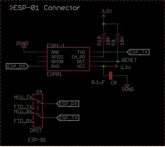
ESP-01 Connector:
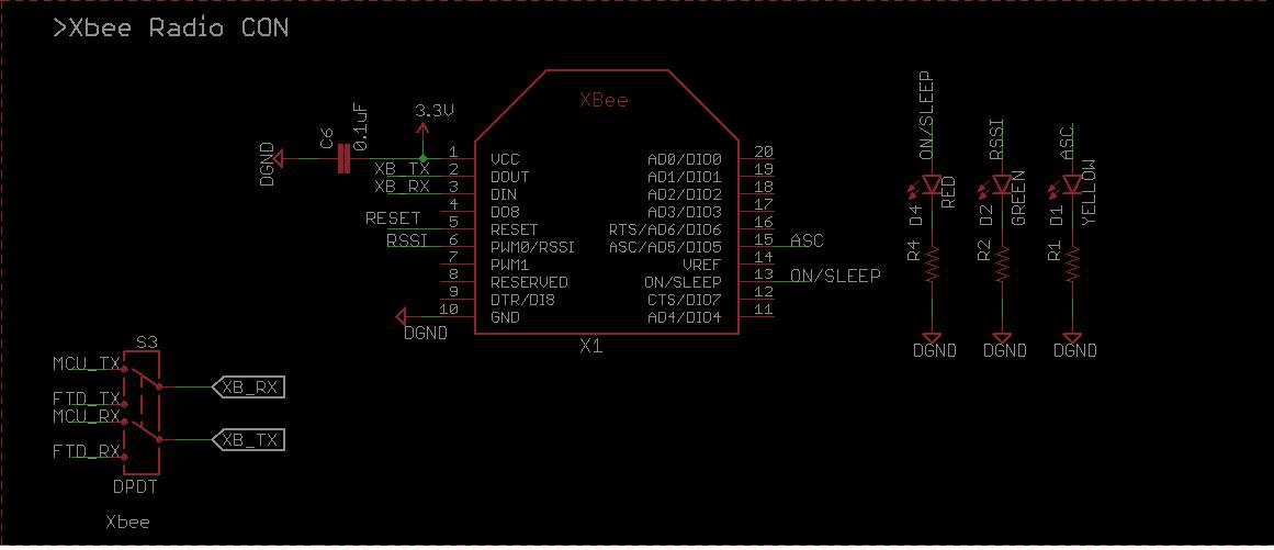
DPDT Switch has been added for both w-less connectivity. This will allow to access w-less module either over MCU for application or over PC terminal for configuration.
Xbee Connector:
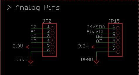
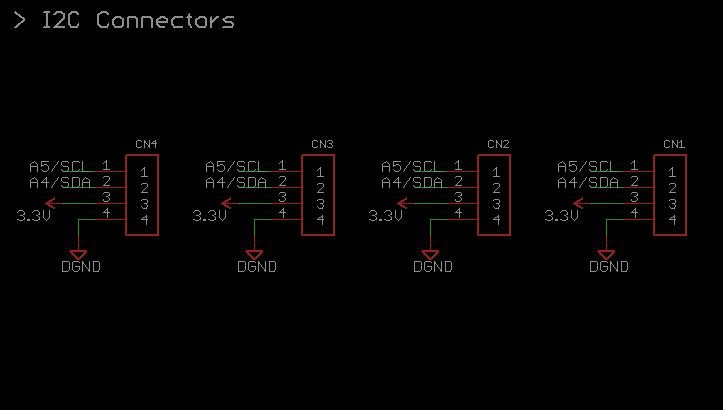
GPIO:
- ANALOG:
- DIGITAL:
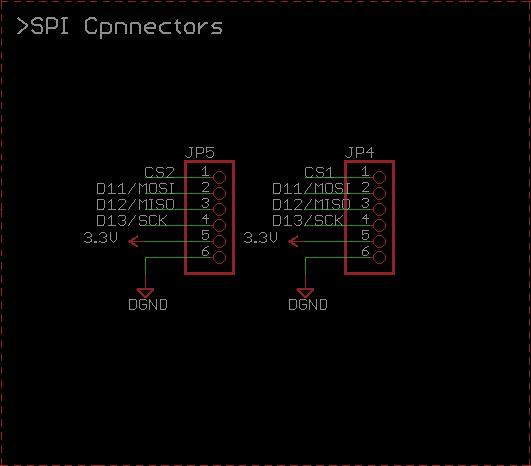
- I2C & SPI:
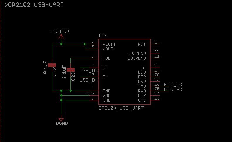
- USB-to-UART: CP2102
 Amar Potdar

Discussions
Become a Hackaday.io Member
Create an account to leave a comment. Already have an account? Log In.