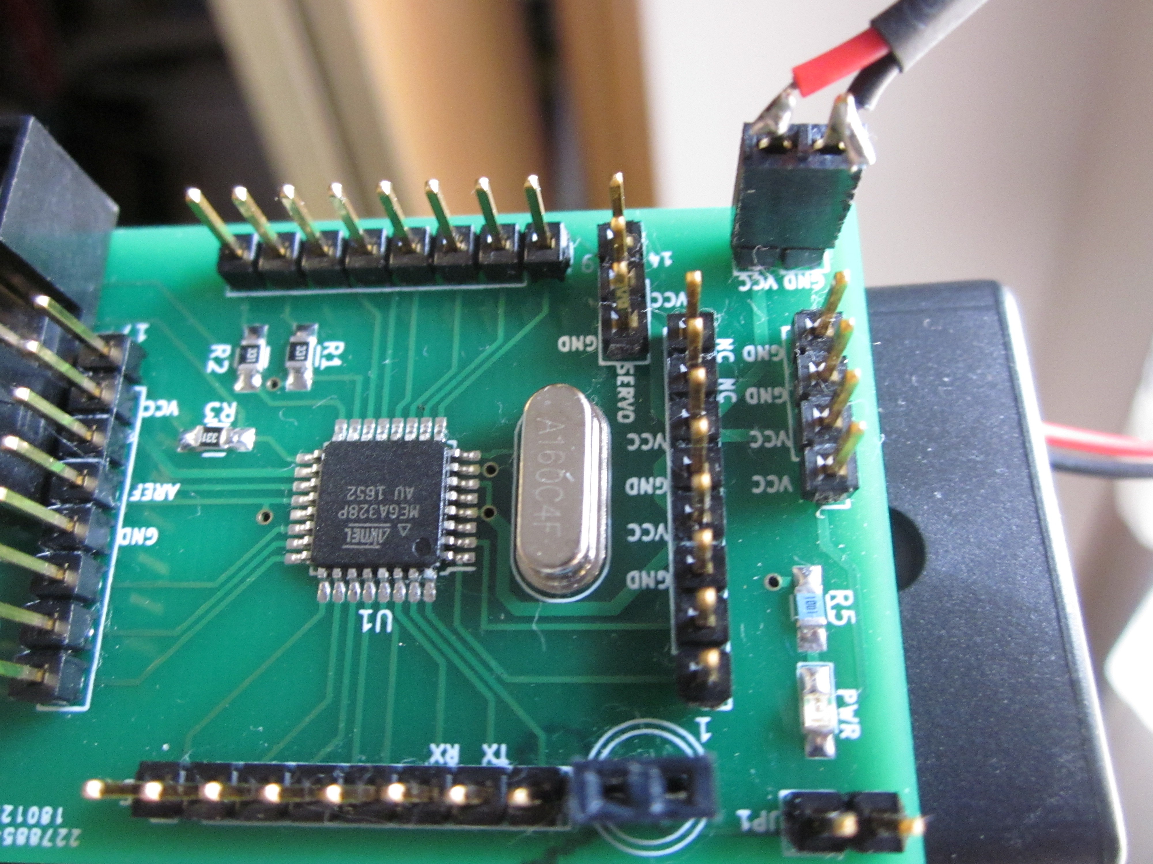
Some time ago I bought some 2 AA battery holders that were little over $1 USD for two. For the Atmega328P, the minimum operating voltage is 1.8V, allowing it to be run on 2 AAs. An important note is that according to the datasheet, you can't exactly run it at 20 MHz with 2.4-3V which is why I assembled a board using a 4MHz crystal.
I didn't want to permanently solder a battery holder to the board so I decided to solder a 2-pin .1" header to the wires of the battery holder, making a plug or sorts. On the board there is a 2-pin male header that of course has VCC and GND. I could have used a 2-pin female header on the board and just pushed the battery holder wires into that, but based on past experience the resulting connection tends to be iffy at best. A downside is that since there is no keying, you have to be careful not the plug it in backwards.

Discussions
Become a Hackaday.io Member
Create an account to leave a comment. Already have an account? Log In.