So people kept telling me I should keep the programmer external and not burden every board with the cost and size penalty for having the programming circuitry on every board.
While I very much agreed in theory (for most boards, once installed, the USB would never be used again), there was the issue that there doesn't seem to be a good "standard" external programming solution I could find in the market! The only two I could find use the CH340 chip, which I'm avoiding since installing the driver bricked my friend's Mac.
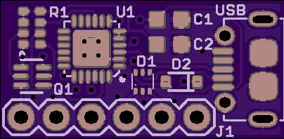
The more I thought about it, the more the solution became obvious: if something doesn't exist, I guess I have to make my own. :) So I did:


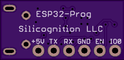
This is about the simplest CP2102N based programmer circuit I could come up with, reduced to the bare minimum. It has a footprint for a single line header, the idea is that this will be populated with a right angle header so the optional USB programming / UART module can be installed at a 90 degree angle to the main board and require a minimum amount of space on the main board.
The main board will have a footprint like this:

This is from the Sparkfun Eagle library. The holes are staggered just the right amount that a pin header will lock in place when you just push it in. For a dev board, or in a use case where you actually want the USB port, you just push it in and solder it to make it permanent. In case you just want to program a board and not have the USB in the application, you can push it in, program the board and pull it out again. You can of course also install a female header if you want, but this is supposed to make that unnecessary.
So what do you all think? Good solution? It should make everyone asking to not have the programmer on the board happy as well as those who do want the USB to UART for their application.
I have prototype PCBs on order, once I have built them and tested to make sure it all works, I will make the design files available. I will produce these myself if necessary but this is such a basic thing that I hope others will produce clones and this can become some form of ESP32 programmer standard. It's kind of silly that every ESP32 board out there needs to reproduce this stuff...
I wonder: should I make this its own project on Hackaday.io as well? Maybe I should.
 Patrick Van Oosterwijck
Discussions
Become a Hackaday.io Member
Create an account to leave a comment. Already have an account? Log In.
For reference for people like me who aren't using Eagle, it looks like the pins are each offset 0.005" from the center line on that staggered footprint, for a total of 0.010" difference between even and odd pins.
Are you sure? yes | no
Yes, I can confirm this is the case, thanks for adding this useful info!
I'm using the 1X06_LOCK footprint from the Sparkfun-Connectors Eagle library.
To add a bit more info: how well it locks seems to vary a bit. Some are solid enough to use just pushed in, others are just tight enough to not fall out but tend to shift with a USB cable attached. In all cases it's helpful enough to keep the module in place while soldering it in though. :)
Are you sure? yes | no
oh damn, I wish I'd seen this a couple weeks ago. I would have made my programming pins for the #uMesh match these. Next time!
I'll probably pick up one of these anyway, if the designs are up :)
Are you sure? yes | no
Hi,
seams we working on something similar. My design using the CP2104 with a smaller QFN footprint (QFN24) and also add a voltage regulator and the pin header are at the end. Your board also seems to include a autoreset with Q1 (dual trasistor/mosfet) ?
Main purpose maybe the same: build a esp32 board with just a programming pin header.
here are some Tweets about my status:
https://twitter.com/pcbreflux/status/961909049674620929
https://twitter.com/pcbreflux/status/961910669003100160
https://twitter.com/pcbreflux/status/978578032746254336
https://twitter.com/pcbreflux/status/980820242061553664
https://twitter.com/pcbreflux/status/980824098061381632
https://twitter.com/pcbreflux/status/980825522119888896
Thanks for sharing and yes please commit a own project
pcbreflux
Are you sure? yes | no
Nice! Yes, seems very similar. The Q1 on mine is indeed a dual NPN for the auto reset function.
I put the header on the side of mine because the goal is to be able to install it as a component onto a main board, with the USB facing the side of the board.
Are you sure? yes | no
I have been looking for something similar for some time. Please take a look at the official ref design of the ESP-Prog:
https://github.com/espressif/esp-iot-solution/blob/master/documents/evaluation_boards/ESP-Prog_guide_en.md
This could be a very interesting and standalone project if you follow it or adapt some things from it. Take a look for example at the Automatic Downloading Function and the Delay Circuit. It also has JTAG functionality apart from serial programming.
I contacted Espressif and they told me that no one is manufacturing this yet, that they know, not even themselves.
Are you sure? yes | no
Thanks for the link! I do have the auto downloading function on mine, that's what Q1 (dual NPN) and R1 (4 x 10K) are for.
Are you sure? yes | no