 Patrick Van Oosterwijck
I've been referencing this "other similar project" (ESP32 with PoE Ethernet) that I've been working on for a customer. I consider it somewhat of a prototype for what I'm trying to do with the wESP32. Well, I've been working on that and in the interest of showing that it's all very possible, I now have a working prototype of that project:
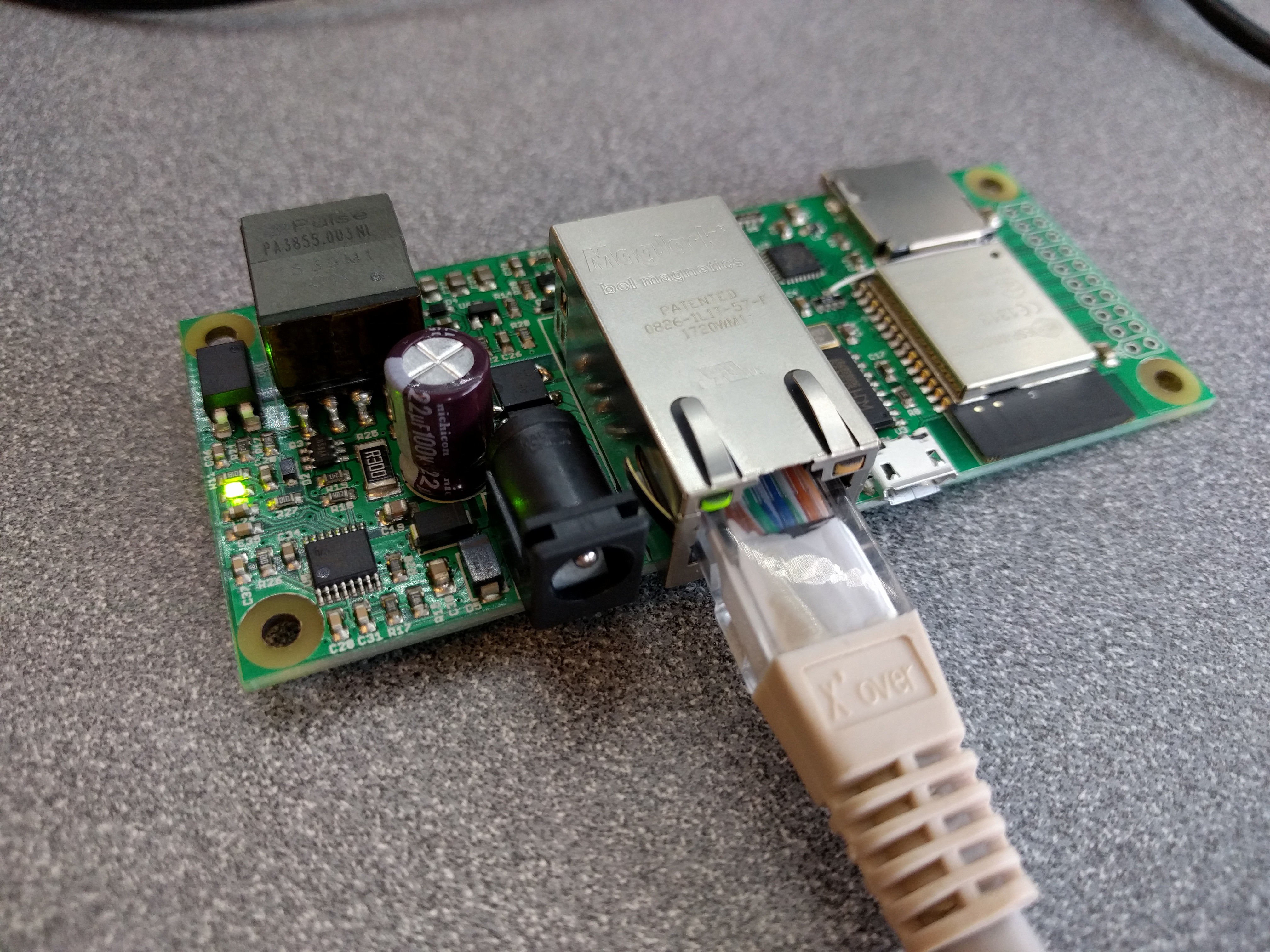
At the moment this board has MicroPython on it and can successfully "GET" a web page over Ethernet.
Here's what I want to do different for wESP32:
- Make the isolated power section more compact by using the Si3404, dropping the barrel jack power input and using smaller components where practical. If someone needs to have it in a place where they can't run PoE, a local 802.3af power injector and WiFi can still be used.
- Use a smaller, lower cost Ethernet jack that's still compatible with PoE.
- Replace the CH340G USB programming interface either with a CP2102N or an external "ESP32 programmer".
Several people have told me to make the programming circuitry external. Unfortunately, external "ESP32 programmers" seem to be very rare. There's this one from AnalogLamb but it uses the same CH340G that I'm trying to avoid because it has issues with Macs (it bricked my friend's Macbook). I can't find any other one. Does anyone know of such a thing?
Or does anyone have a strong opinion the other way: they really want built-in USB programming and serial port? One advantage is that it's another way to provide local power if there's no PoE, although the "12V" rail will only be 5V in that case...
Of course, there's also the option to make my own. Just what I need: yet another project. :) - Remove the SD card slot. It shares GPIOs with the GPIO header, so if someone needs it, I figure they can add it to their own custom circuitry.
Thoughts and comments welcome! Project "likes" are very welcome too, since they translate to seed funding at this point. :)
Discussions
Become a Hackaday.io Member
Create an account to leave a comment. Already have an account? Log In.
Do you have any indication yet of what the I/O layout will be? im looking at building out some smart light switches and relay/PWM modules using these. sorry to hassle you.
Are you sure? yes | no
No worries, customer conversations are very welcome at this stage! Better to build what the customers want than to guess.
I haven't decided yet what the I/O layout will be. The customer prototype I have has all I/O on a double row header on one side, because they need to be able to plug a board in on the end with a right angle header. Or it can be used with a straight header to plug in an application specific daughter board on top. That's one possibility.
Another is to have a single row of I/Os on both sides of the ESP32 module, like most other board do. That way it could be breadboard compatible.
Which one works best may become apparent once I have a schematic and start floor planning. Do you have any preference? Anyone else have a strong opinion either way?
Are you sure? yes | no
Nice - my preference would be a double header at one end of the board and the ethernet jack at the opposite end, so i could plug it directly over a board like that (idea being that it piggy backs a pcb for a smart light switch and fits inside a wall flush box) thanks!
Are you sure? yes | no
Did you check my floorplan in this update: https://hackaday.io/project/85389-wesp32-wired-esp32-with-ethernet-and-poe/log/142477-progress-floorplan-some-layout ? Seems the double row header at the end is the way to go.
Are you sure? yes | no
Nice! Let me know when you have new design done. What pins are you going to make available?
Are you sure? yes | no
Most likely all pins not in use for the Ethernet RMII MAC. Most of those are on fixed I/Os (19, 21, 22, 25, 26, 27) but MDC and MDIO can be mapped to any I/O and which ones I'll use will depend on what makes sense in the layout.
Are there any pins you really need to have available for a particular application?
Are you sure? yes | no