Well I've been wrong before and I was wrong this time too, I re-examined the original paper that I sited for this project because I felt something wasn't quite right, and I wasn't too far off the mark. What I missed was in their initial setup they have a pinhole diaphram as a beam shaper before the laser strikes the sample, hence forgoing a "real" laser collimator, this actually is still fine (although it would of been better if they would have given the dimensions for the pinhole size, but I figured it out through trial and error...)
Dimensions are: 0.6mm/0.02" in diameter
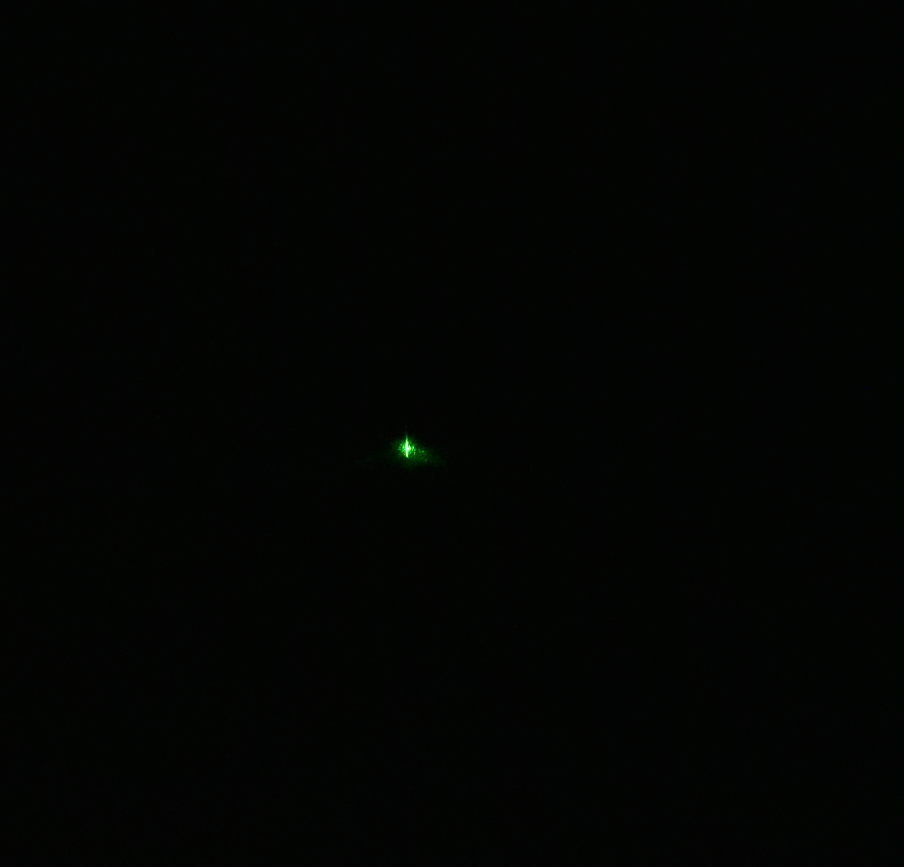
This is the raw jpeg image, zoomed by 50X to show the actual laser point (TEM00)

Looks awesome huh? Almost like the Sun, if U look close you can see a finger print on the diffraction grating to the far left...oops
Below is the actual spectrum as seen by the detector

Below is the plot, the FWHM value (full width half maximum,) of the beam is 1.5nm!


The DSLR camera settings were as follows:
F-stop @ 10
Exposure time @ 1/30 sec
ISO @ 7200
Exposure bias @ -5 step
35mm focal length
I am incorporating the pinhole mount to fit into the laser guide component block for the Raman probe and will have a proper build log when I have ALL components printed as I keep re-designing out of necessity.
 David H Haffner Sr
Discussions
Become a Hackaday.io Member
Create an account to leave a comment. Already have an account? Log In.