Close
0%
0%

Reflow Oven

A Netduino-based solder reflow oven built from an old toaster oven

Similar projects worth following
A solder reflow oven that was built out of existing toaster oven. The design goal was to create a fully self-contained oven with no visible modifications - the product would have to look, like it had always been this way!

The Oven has basic web support, offering a basic web page and Json feed with various information about the oven, including run state, temperatures, system faults, and overall status.

This project uses some libraries and code snippets made available publically on github and on the Netduino forums. The main third-party library used is Fredrik Rinsén's WebServer library for Netduino. As well, I use an I2C Bus code file by Pavel Bansky and phantomtypist, and lastly CPU load estimation by inquisitor.

As for what this project is going to be used for? It's in use at MakerSpace Nanaimo!

Where it is

Want to check out the reflow oven? Drop by MakerSpace Nanaimo!

The Brains

The reflow oven uses a Netduino Plus 2 as its main microcontroller. This board directly connects to most of the hardware in the oven. The only things it doesn't connect directly to are the IGBT driver and the door switch, as these are connected through an I2C port expander. This processor normally runs around ~30% CPU load when idle and around 70-80% load during reflow.

The software running the oven is C#, written with Visual Studio 2012 Pro and then VS 2013 Community. It is multithreaded, with one thread running the main process loop and GUI while other threads handle the PID controllers and SSR switching.

The Brawn

The oven itself is powered at 120v, feeding two element banks. There are two resistive elements at the bottom of the oven, and a pair of quartz elements on the top. These are controlled by a pair of 12A SSRs - one for the upper elements, one for the lower elements; when cold the oven can draw over 16A!

The SSRs are switched at roughly 125Hz (not 120Hz due to integer limitations in timing), with the zero-crossing circuitry in the SSRs handling precise phase sync.

Two fans cool the oven. One is directly powered from the 9vdc transformer and runs continuously to maintain a small but steady flow of cool air into the electronics bay. The other fan is controlled by software to provide cooling capacity to the oven during the cooling phase.

The Interface

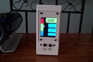
The interface is a combination of the original toaster keypad (with liberal application of a dremel to break all the circuit connections) and an Adafruit IL9340-based LCD. It allows for a nice splash screen, visual feedback and guidance through the menus, and a full graph of every reflow operation from start to finish.

Fun fact: there is more VRAM available to the LCD than there is normal RAM available to the microcontroller program!

The Web

The oven maintains a simple web presence via a static HTML page with a small amount of javascript, and a Json feed that is provided for the aforementioned javascript and for external tools, that lists out various statistics of the oven including temperature readings, element power levels, fan status, operating mode, and more.

  • 2 × 12A SSR 12A zero-crossing SSRs a coworker handed to me on a job site
  • 2 × Netduino Plus 2 I blew the first one up
  • 1 × Toaster Oven It gets hot
  • 1 × Basic PC Fan Cools the electronics bay
  • 1 × PWM PC Fan Controllable fan for cooling the oven

View all 12 components

  • SPI Troubles

    Sukasa07/31/2016 at 17:12 0 comments

    Looks like I'm going to have to fix another problem that's come up. In addition to the previously-mentioned overheating issue, the controller seems to occasionally fart and mis-read the temperature sensors, thinking it's suddenly become way too hot. I'm going to have to look at the code and add some filtering, so that it doesn't immediately fail if it gets a reading that is too hot.

    I'd also like to figure out what is causing it to trip directly. Could be a power bump (the makerspace has notoriously bad power quality), or something else.

  • Remote File Access

    Sukasa07/31/2016 at 17:09 0 comments

    Well, it's done. The controller now plays (mostly) nice over the network and allows me to browse folders, upload & download files, and read status information over the network. It makes it a lot easier to manage what's on the SD card. No more grabbing a screwdriver when I need to fiddle with a text file!

    Of course, one of the other members at the makerspace thinks I'm just gilding the lily at this point, but I still disagree ;)

    The next step will definitely be to fix the insulation, as repeated use of the oven is showing that the electronics bay is overheating too easily and the system is shutting down on thermal safety. Not much fun when you're halfway through a reflow and the controller aborts the run because it's too hot.

  • ​Further Tweaks

    Sukasa11/26/2015 at 23:03 0 comments

    Well, after having used this oven a couple times, it's clear I could use a few more tweaks to the thing.

    First off, and it's been mentioned before, is the thermal insulation in the oven. More reflect-a-gold to improve the heating in the oven and keep a little more of it from being lost through the oven walls. I could also probably insulate it better with insulation along the outside of the oven, especially along the top.

    Second, I've noticed that the heating isn't perfectly even along the edges of PCBs. The reflect-a-gold might help with that, but if not I'll have to look at a way to deal with this that isn't just "leave a nice lip at the edge of the PCB". More thought will be required on that front.

    Third, updating the profiles is a pain. It's easy to update the firmware via MFDeploy over USB, but updating anything on the SD card currently requires me to remove the cover of the oven to access the electronics bay and remove the SD card (which itself has a ~40% chance of causing the uC to crash and start playing greensleeves). I might try to create an extra class that lets me read and write data to the card, as well as return folder lists. Would make for a nice little side-project to release independently.

  • On SPI Buses and Rogue Pull-ups

    Sukasa11/23/2015 at 19:44 0 comments

    This was quite an interesting and Fun bug to track down, as it was a mix of software and hardware issues that led to it.

    I first noticed this bug after running my oven with its LCD for the first time. I could send it commands well enough, and I could read and write data, but... There was corruption in just the video data going to the LCD. I initially thought it was a bad LCD, however that was quickly proven false after testing it outside of the oven.

    It was a fairly distinctive corruption however, and I soon figured out what it was - every time I tried to read a block of data from the display a single bit of information would somehow be skipped. Everything would be shifted left a bit and the resulting data, after being read in and modified (ex for text rendering) would be written back to the display corrupted. The number of bits it was shifted by, amazingly, appeared to be related to the number of separate read/write commands I sent to the LCD!

    After writing some software workarounds that fixed the data (thankfully the missed bit would always be 0 and thus wasn't worth worrying about) at the expense of performance, I set about trying to figure out the issue. There was a software component to it, but.. the culprit seemed to be in the hardware, as the code worked fine outside of the oven!

    There were only 3 devices on the SPI bus. The LCD, and the two thermocouples. Process of elimination meant that the SPI thermocouple breakouts were to blame, but how? I went over their circuits looking for an answer, and found it. The thermocouple units had pull-up resistors attached to the clock and data lines!

    Now it started to make sense. Because the SPI code on the Netduino was in MSIL, it meant that it had to run through an interpreter in the board's firmware before anything could be executed... which was just long enough between the command-write and the data-read that the Netduino's SClk pin would be left floating instead of pulled down.. and the pull-ups on the thermocouples would then take over and assert the bus HIGH.. and then the Netduino would finish executing enough code and pull the bus low in preparation for the read.. which made the LCD output a single bit that the Netduino would never read.

    In the end, I fixed it. By using a transistor on the SClk line to isolate the pullups from the LCD and Netduino. The problem went away, the workaround wasn't needed, and all was happy.

    And I'm not going to use those thermocouple modules again.

  • Things not to do with a Netduino

    Sukasa11/23/2015 at 19:31 0 comments

    When you're using a Netduino, don't...

    • Drop a wire across the 'clear flash' contacts
    • Send it TCP connection requests before it's booted
    • Try to allocate 32768 bytes three times over
    • Let it crash with the elements at 100%
    • Try to low-side switch something being fed with 9v
    • Forget the pull-up resistors on I²C
    • Use SPI slave devices that pull up on the clock line
    • Short +9v to the +3.3v rail. You'll let out the magic smoke, and nothing you did above will matter now.

  • Overheats

    Sukasa11/23/2015 at 19:23 0 comments

    This one will probably be something I revisit over time. The issue? Temperature in the electronics bay.

    See, the problem with reflow ovens is that they tend to get hot.. after all, that's what a reflow oven is meant to do. And electronics don't like being too hot. Now most people solve this by moving their electronics outside of the oven to cooler climes. Sure, that does work but it's at odds with one of my goals with this project which was to present a much more 'finished' look to the project.

    My first thought was simple - just use a cooling fan. Problem solved, right? Wrong. The flow of cool air into the bay doesn't actually cool as much as I'd like, and the temperature sensors picked up on it - between radiant/convective heat from the oven and the heat produced by the SSRs, the electronics bay can get up to 50°C right now. I can also get easily above that, but I chose 50° as my safe cut-off temperature.

    So in terms of ways to fix this.. I think I can probably improve the insulation around the oven a bit more - once I get some cash for more reflect-a-gold. Another thing that did help noticeably was to drill a series of vent holes directly above the air gap between the oven wall and the shield protecting the mounting plate from the oven, giving the hot air a direct escape path. Expanding the vent might help further and is definitely worth doing.

  • Getting the temperature right

    Sukasa11/23/2015 at 19:15 0 comments

    One of the challenges I faced at one point was getting the temperature of the oven to where it needed to be. While I could get to just about any temperature fairly easily, the problem I had was that the higher temperatures were a bit difficult to get to quickly. The problem was that there was a lag between applying power to the elements and getting heat from them. While the lag was fairly small at low temperature, at higher temperatures the lag could be on the order of 10-20 seconds.

    My solution was pretty simple. I added a flag for certain data points in the profile that, when hit, would command the oven to look an extra step further ahead in the profile and aim to hit that temperature, while displaying the 'normal' temperature setpoint. This little bit of sleight-of-hand allows me to overcome the effect of the lag, while still presenting the intended temperature curve to the user (and indeed, achieving that curve).

View all 7 project logs

Enjoy this project?

Share

Discussions

Martin wrote 11/30/2015 at 11:44 point

Regarding the "rogue" pull ups:

Basically you can use SPI in 4 modes, regarding clock phase and polarity (CPOL, CPHAS). The most (normally) used configuration is 0,0; that means, the idle state of the clock line is "low" and therefore many datasheets for SPI devices recommend using a PULL DOWN on the CLK line. And a pull up on the chip enable. So somebody did not think very far by constructing this modules. Unfortunately this is not the first time I experienced similar with an adafruit module.
Instead of a cludge with an additional transistor, I would have removed tho offending Pull Ups and used a pull down on the CLK line.

  Are you sure? yes | no

ianlee74 wrote 11/28/2015 at 16:02 point

Nice project.  I started one with a similar goal (fit commercial interface, NETMF based) about a year ago but had to shelve it due to other projects.  One question, though, concerning your SD card problem...  Why do you even need the SD card?  I can't imagine your program with profiles is so large that it won't fit in the Netduino flash space and if it is then perhaps you should consider moving to a GHI Electronics board that typically has much more flash space.

  Are you sure? yes | no

Sukasa wrote 11/28/2015 at 20:41 point

The SD card is used to hold the graphics for the screen (~150KB each that I stream to the LCD, and there are 6 of those, plus smaller resources here and there), and so that when editing profiles I can just pop the SD card into my laptop and edit them in notepad.  Makes it a lot easier to tweak things.

  Are you sure? yes | no

ianlee74 wrote 11/28/2015 at 21:47 point

I thought that might be it but most of what I saw in the few screenshots appeared to be drawn in code except for the logo. Perhaps just add on an external SD card reader and mount it near the edge where it can be accessed externally.  Or move to something like a FEZ Cobra III that has 2.8MB of flash space and move the images to flash if there aren't too many.

https://www.ghielectronics.com/catalog/netmf

  Are you sure? yes | no

Similar Projects

Does this project spark your interest?

Become a member to follow this project and never miss any updates