There were a few hiccups along the way that I thought I would share for the benefit of future hackers.
Initial Design Problems
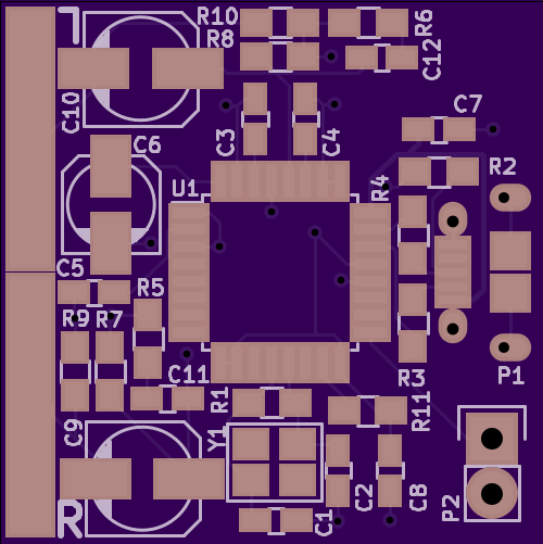
One of the first challenges was having eyes bigger than my PCB. This project is an entrant in the Square Inch Project so I was limited to a 1"x1" PCB. I really only need playback, but after looking at various interface ICs, I thought it would be neat to have a 2 input 2 output interface with a switch to change the plugs between playback and recording. When It came time to do the board layout I could make it all fit. So I scaled everything back down to my original idea and was able to get everything to fit.
USB Connector Mounting Holes
The USB connector datasheet specifies, and I had created a footprint including plated slotted holes for the shield studs, however, OSH Park does not support plated slots. Now I already knew this, but through some absent-mindedness I did not remember when I was designing it and further more did not notice that the slots were converted to holes in the preview when I submitted the gerbers.

I ended up working around this by bending up the studs and turning it into surface mount connector and soldering those studs on top of the pad. The lesson learned here is to double check the preview you get back from OSH Park, it is pretty accurate.
Further USB Connector Woes
Unfortunately without the holes, there is no way to keep the connector aligned. With the pin pitch of the connector and with the connector pins basically being under the pad, this made the reflow of the connector a little more error prone and made rework a lot more tricky.
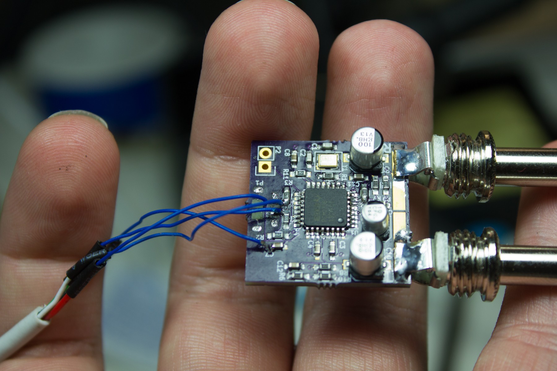
On my first board there ended up being a short between a couple of pins. After various attempts to reflow, rework, desolder, and resolder this connector, I had mangled up the board pretty bad and torn up a few pads. Eventually I resorted to just soldering a USB A pigtail to various pads directly on the board to give me this monstrosity:

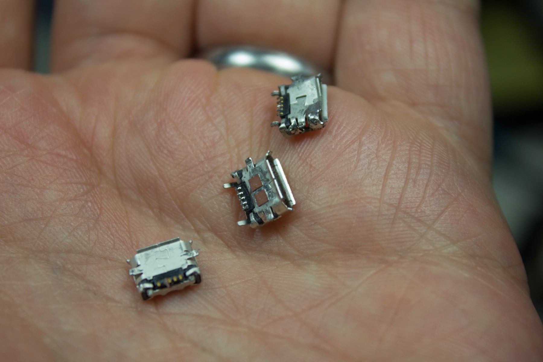
Leaving behind a trail of mangled USB Micro B connectors.

Thankfully with lessons learned in dealing with Micro B connectors, the next two boards were assembled just fine.
 Jacob Creedon
Discussions
Become a Hackaday.io Member
Create an account to leave a comment. Already have an account? Log In.