 jaromir.sukuba
Today I made some updates to this project:
- the programmer functionality is actually tested on my 25x25mm hardware, not just on generic arduino board
- BOM is available not just as parts list here on project site, but also on github
- PIC16F1829, PIC16F1825, PIC16LF1829 and PIC16LF1825 are added to supported devices list on current software
Then I set up simple project in MPLABX with main.c
#include <xc.h>
#define    _XTAL_FREQ    (2000000*1)

#pragma config FOSC = INTOSC
#pragma config WDTE = OFF
#pragma config PWRTE = ON
#pragma config MCLRE = ON
#pragma config BOREN = OFF
#pragma config PLLEN = OFF
#pragma config BORV = LO
#pragma config LVP = ON

void main(void)
    {
    OSCCON = 0x60;
    TRISBbits.TRISB6 = 0;
    while (1)
        {
        LATBbits.LATB6 = 1;
        __delay_ms(100);
        LATBbits.LATB6 = 0;
        __delay_ms(100);
        }
    }
doing nothing but setting up config bits and blinking a LED connected to pin RB6 and set up experiment board accordingly
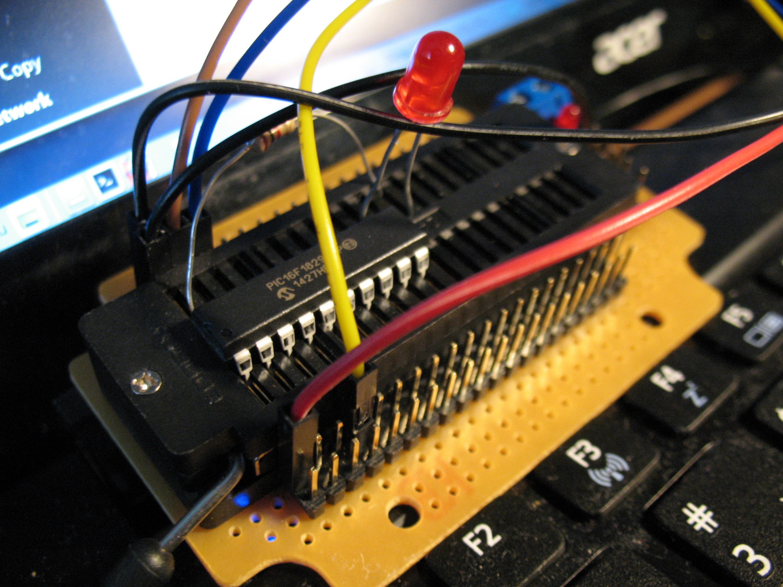
Nothing but LED on RB6, in series with resistor, programming cables leading to my programmer.
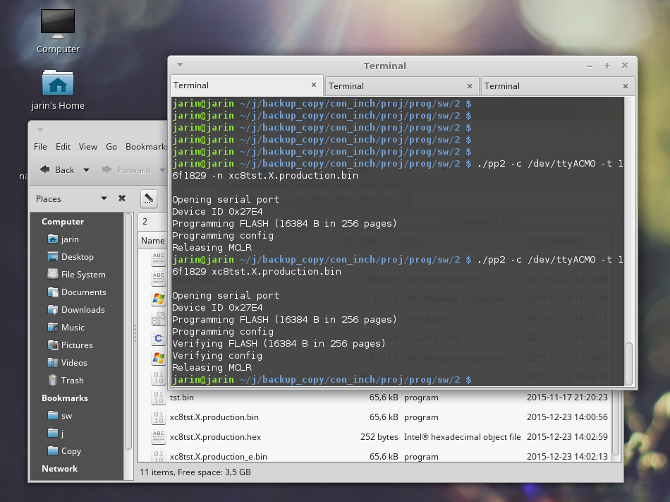
MPLABX generated hex file and using bin2hex program - windows version is available here - I converted the hex file to binary. And after running
./pp2 -c /dev/ttyACM0 -t 16f1829 xc8tst.X.production.bin
from where pp2 binary and bin file to program resides - believe or not - it worked flawlessly on first try.
and LED blinked, as captured on this crappy video
Sorry for that video quality, but my favorite camera is out of order now.
Windows users should enter something like
pp2 -c COM30 -t 16f1829 xc8tst.X.production.binwhere COM30 is COM port created by the device. It is tested on win7 64-bit.
Discussions
Become a Hackaday.io Member
Create an account to leave a comment. Already have an account? Log In.