 jaromir.sukuba
In case you'd like to build it, you have two possibilities when it comes to hardware - use off the shelf arduino board or build dedicated hardware.
Hardware option 1 - Arduino hardware
Take any Arduino with ATmega328P, like Uno or most of cheap chinese knock-off boards. Considering the target has its own power supply, connect GND, MCLR, PGC and PGD lines to respective pins on arduino as follows:
| Arduino pin | = AVR pin | Target PIC pin | Comment |
| GND | GND | GND | ground |
| 5V | VDD | VDD | * optional - power supply for PIC MCU you may power target from other source |
| A3 | PC3 | MCLR | reset line of PIC MCU |
| A1 | PC1 | PGD | programming data line |
| A0 | PC0 | PGC | programming clock line |
* If you are powering target PIC from other power source (in circuit programming), series resistors (something like 470-1000 Ohms) in MCLR, PGC and PGD lines are good idea, it will somehow decrease currents flowing through IO pins due to power supplies differences between arduino and target board. In this configuration, even targets running at 3,3V are possible to program, though it is dirty practice.
Power it up, no smoke should be released. Run arduino IDE, open programmer firmware from github, complie and upload to arduino board - now you have PIC programmer ready to go. Go to software below.
Hardware option 2 - dedicated board
Considering the target has its own power supply, connect GND, MCLR, PGC and PGD lines to respective pins on PIC programmer (notice the pinout similar to PICkit programmers). Vdd line is not currently used ad it is not needed for operation of programmer, but future revisions of firmware may take advantage of this pin and detect target VDD.
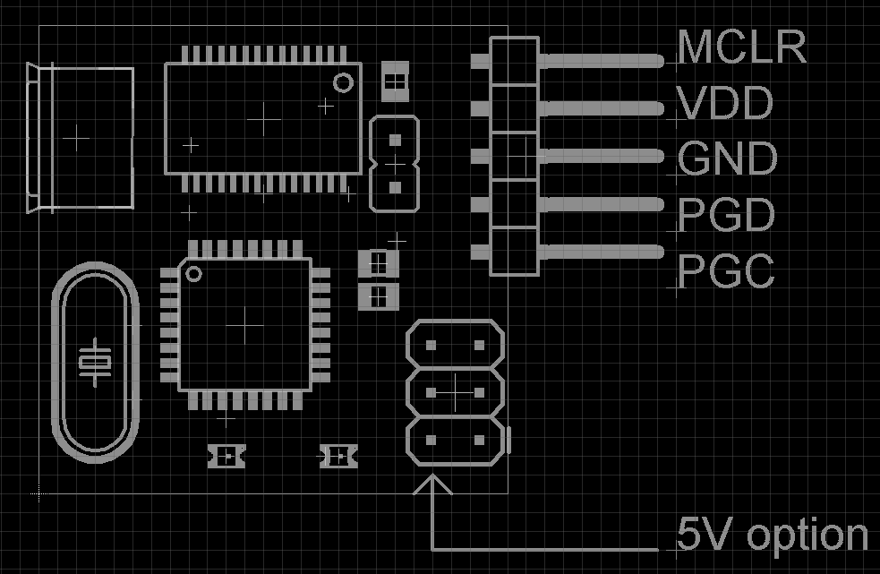
If you wish to power the target from programmer, you can use 5V from AVR ISP connector.
Use another arduino or ISP programmer to load Arduino UNO bootloader to PIC programmer board (performed onle once), turning it into regular arduino.
Ensure JP2 is closed, then you can load new firmware into PIC programmer using regular Arduino IDE. Open jumper JP2. Now you have your programmer ready to go, move on to software.
Software
When running under Linux, download source from github and run
gcc -Wall pp2.c -o pp2This should buiild executable pp2.
Under windows, you can download binary from github. Alternatively, you can build it from source - install minGW and run
gcc -Wall pp2.c -o pp2
- the same procedure as on Linux. This should result in silent build with pp2.exe executable created.
Running the executable with no parameters should only bring banner pp programmer.
If you have .hex file ready to program into PIC, convert it to binary file using utility hex2bin, available here for windows - using command
hex2bin -e bin file.hexresulting in file.bin creation.
Now, having functional pp2 software and binary to be downloaded, run command
./pp2 -c /dev/ttyACM0 -t 16f1829 file.bin
under Linux, where -c parameter denotes port to be accessed, -t parameter defines PIC to be programmed and last parameter is binary file to be downloaded; or
pp2.exe -c COM30 -t 16f1829 file.bin
under Windows to run the actual software. And program the target PIC.
The result should look like this:
$ ./pp2 -c /dev/ttyACM0 -t 16f1829 file.bin

Opening serial port
Device ID 0x27E4
Programming FLASH (16384 B in 256 pages)
Programming config
Verifying FLASH (16384 B in 256 pages)
Verifying config
Releasing MCLR
And now your PIC should be programmed and running.
Notes on software
If you are running the hardware on generic arduino board or you forget to open jumper JP2 after loading firmware on dedicated hardware, you may need to insert waiting time after opening serial port and before communication - to ensure Arduino bootloader times out and takes control to programmer firmware. It should look like this
pp2.exe -c COM30 -s 1700 -t 16f1829 file.bin
where number after -s switch defines the number of miliseconds to wait after opening the serial port.
You may omit the actual programming using -p switch or verification using -n switch, when using both the programmer only checks target device signature and exits.
$ ./pp2 -c /dev/ttyACM0 -p -n -t 16f1829 file.bin

Opening serial port
Device ID 0x27E4
Releasing MCLR
you can add some debug output info using -v parameter, ranging from -v 1 to -v 4
Discussions
Become a Hackaday.io Member
Create an account to leave a comment. Already have an account? Log In.
Hi Jaromir, I'd like to give this a try but unfortunately I don't have one of the PICs already implemented in pp2.c but instead I have a PIC16F1503 and a PIC16F1454 which should be compatible, right? Looking up the flash size and device ID to add them to pp2.c was pretty straight forward but I don't understand how you got the values for the page sizes. I'd appreciate some help with this so thanks in advance :)
Are you sure? yes | no
Hello, please wait over the weekend, I'll prepare "how-to" for that.
Are you sure? yes | no
Awesome, thanks!
Are you sure? yes | no
Take a look here https://hackaday.io/project/8559-pic16f1xxx-arduino-based-programmer/log/30468-modifying-the-sources-for-new-devices
Are you sure? yes | no
Woohoo! Thank you very much! :)
Are you sure? yes | no