 jaromir.sukuba
I stated in my first log that this one will be only PIC16F1xxx programmer and nothing else. Well and now it isn't true. I added support for PIC18F25K50 and friends, see on github. Believe or not, this MCU is used in #Badge for Hackaday | Belgrade Conference, what a coincidence.
For now the sources are just quick hack of my PIC16F1xxx programmer (which was quick hack on itself) with added functions for PIC18F devices. Oh yes and now the programmer crunches hex files directly, no need to convert it into bin files anymore!
Blink a LED HOWTO, Linux
First, we need to prepare something to be flashed into PIC, then connect hardware and finally flash the binary..
Step one, SDCC
Download and build gputils
$ svn co https://gputils.svn.sourceforge.net/svnroot/gputils/trunk/gputils gputils_svn
$ cd gputils_svn/
$ ./configure
$ sudo make install
Download latest snapshot SDCC and install it: Extract the binary kit to a temporary directory, let's name it sdcc-temporary. Jump here and copy all files to /usr/local, perhaps with root access
# cd sdcc-temporary
# cp -r * /usr/local
Then test both of the components:
# gpasm -v
gpasm-1.4.0 #1107 (Nov 11 2015)
#sdcc -v
SDCC : mcs51/z80/z180/r2k/r3ka/gbz80/tlcs90/ds390/pic16/pic14/TININative/ds400/hc08/s08/stm8 3.5.5 #9380 (Linux)
published under GNU General Public License (GPL)
So far so good.
Step two, build target binary
Take this source
#include "pic18f25k50.h"		//inculde MCU specific headers

#pragma config XINST=OFF		//good old instruction set, don't change this
#pragma config WDTEN = OFF		//we don't need WDT here
#pragma config FOSC = INTOSCIO		//internal oscillator, IO on RA6,7

volatile int i,j;			//declare them volatile, we don't want the compiler to optimize out the delay

void main(void)
{
    OSCCON = 0x70;			//switch the internal oscillator to 16MHz
    ANSELC = 0;				//make all C IO digital
    TRISC = 0x00;			//and make them IO outputs
    while (1)
    {
        LATC = ~ LATC;			//flip all C pins to opposite state
        for (i=0;i<20000;i++) j++;	//and burn some time
    }

}
name it sdcc_blink.c and enter# sdcc --use-non-free -mpic16 -p18f25k50 sdcc_blink.cthis should result into a few generated files, but we are interested in hex file, in my case looking like
:020000040000FA
:1000000002EF00F017EEFFF027EEFFF0F86AA68E81
:10001000A69CE9680E0EEA6E0068ED6A0050FDE1EC
:10002000EE0EF66E000EF76E000EF86E0900F5CFBC
:1000300005F00900F5CF06F034D00900F5CF00F047
:100040000900F5CF01F00900F5CF02F00900090021
:10005000F5CFE9FF0900F5CFEAFF09000900090023
:10006000F5CF03F00900F5CF04F009000900F6CF41
:1000700007F0F7CF08F0F8CF09F000C0F6FF01C095
:10008000F7FF02C0F8FF03D00900F5CFEEFF03062B
:10009000FBE20406F9E207C0F6FF08C0F7FF09C05B
:1000A000F8FF0506CAE20606C8E258EC00F0FFD7E2
:1000B000700ED36E946A0F015D6B8B1E0001606B36
:1000C0000001616B00016151800F320F03E1200ECE
:1000D0000001605DF2E20001623F02D00001632B8B
:1000E0000001603F02D00001612BECD7120001003B
:0E00F000FC00000064000000010000000000A1
:020000040030CA
:0100010028D6
:010003003CC0
:010006008574
:00000001FF
Now we need to setup the programmer itself
Programmer
Take source of pp3.c and build it
# gcc pp3.c -o pp3This should run quietly and produce executable pp3. With no parameters it should print banner and finish.
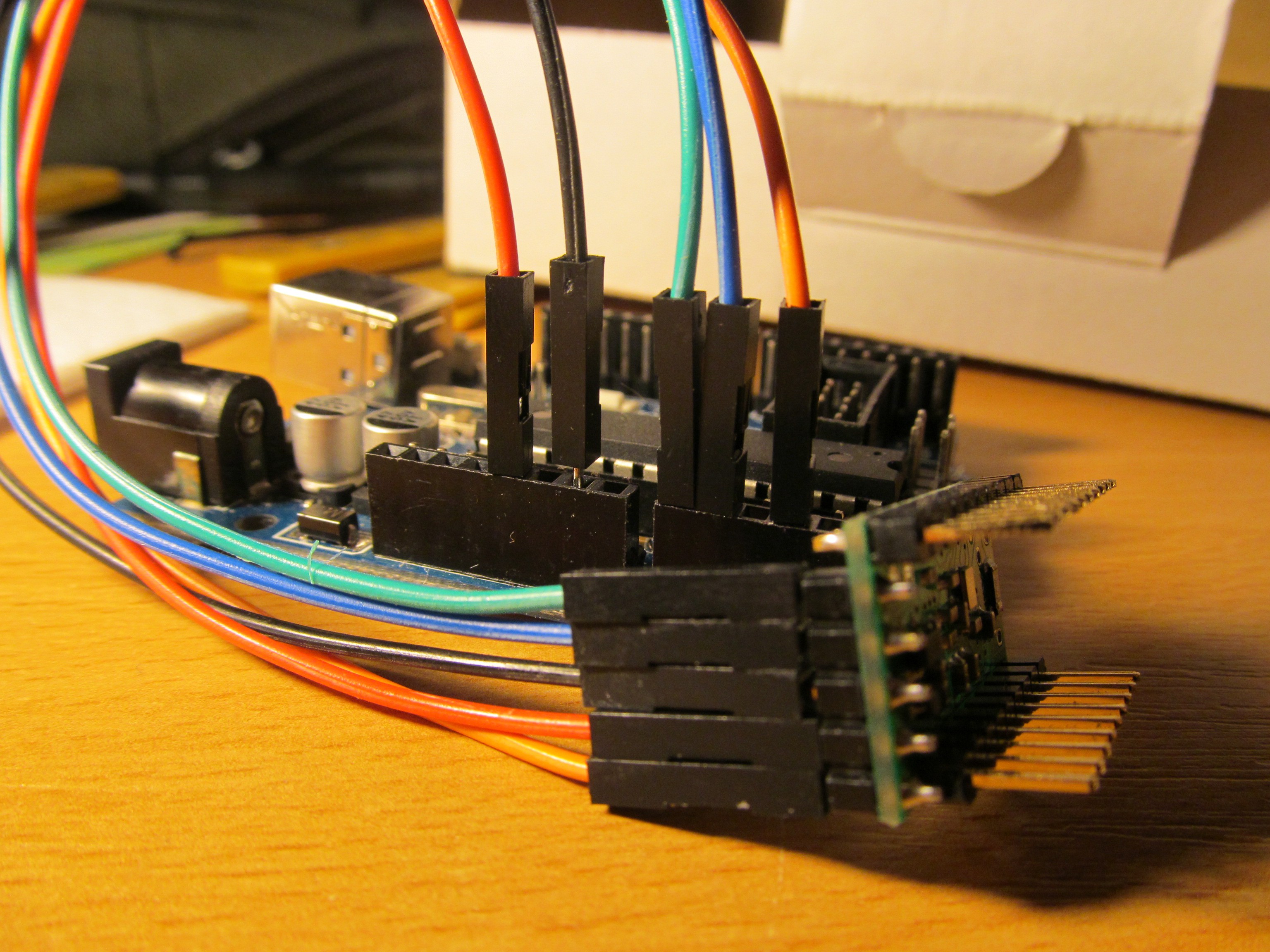
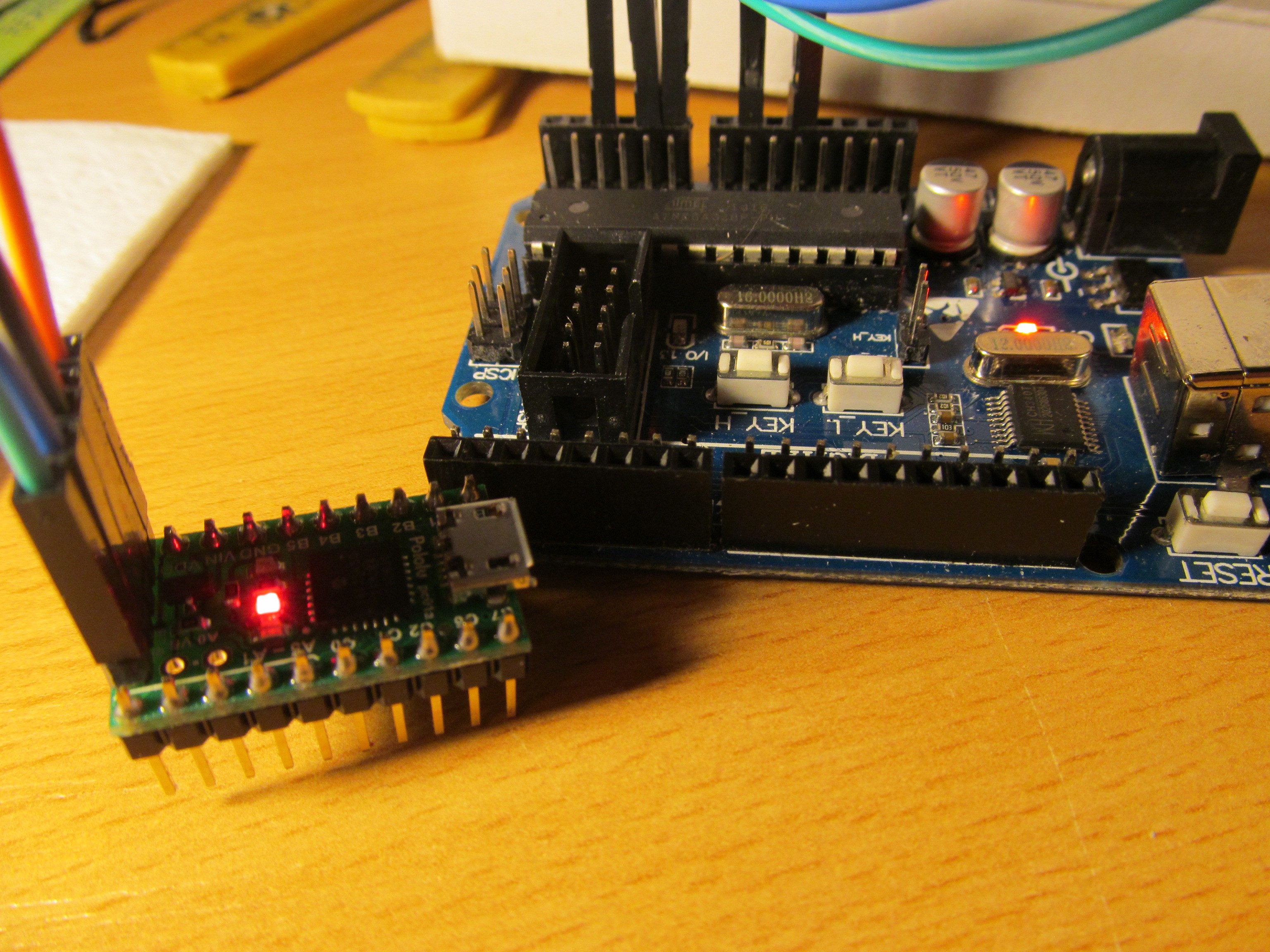
Take arduino and connect A3 to MCLR, A1 as PGD (RB7), A0 as PGC (RB6) of target PIC, plus ground and power from Arduino, for example. I used pololu p-star board with PIC18F25K50
Flash programmer sketch into your arduino.
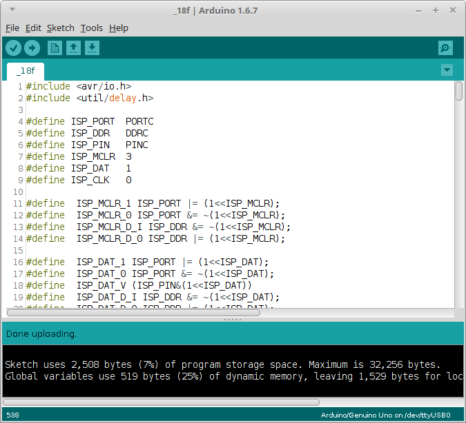
Now you should be ready to flash the PIC
FLASH, Gordon!
Run command
# ./pp3 -c /dev/ttyUSB0 -s 2000 -t 18f25k50 sdcc_blink.hex
and you should get something like
Opening serial port
Sleeping for 2000 ms while arduino bootloader expires
pp
Device ID: 5c20
Programming FLASH (32768 B in 512 pages per 64 bytes):
4 pages programmed
Programming config
Verifying FLASH (32768 B in 512 pages per 64 bytes):
4 pages verified
...and LED should blink.
Now you can make changes in the sdcc_blink.c source and run those two commands to build and reflash the firmware
# sdcc --use-non-free -mpic16 -p18f25k50 sdcc_blink.c
# ./pp3 -c /dev/ttyUSB0 -s 2000 -t 18f25k50 sdcc_blink.hex
Enjoy.
Discussions
Become a Hackaday.io Member
Create an account to leave a comment. Already have an account? Log In.
Hi Again, I had to use my program in Linuz was imposible (to me) run on windows. Well I campile my program using ccs compiler from my mplab on windows, I obtain mi .hex and copy to my linux. Run command to program my pic 16lf1783 and obtain:
Opening serial port
Sleeping for 2000 ms while arduino bootloader expires
pp
Device ID: 2ac0
Programming FLASH (4096 B in 64 pages)
Programming config
Verifying FLASH (4096 B in 64 pages)
Verifying config
config 2 error: E:0x2FFF R:0x0FFF
Can you explain me what could happened?
PD I tried to follow your steps with gcss however I obtain a a message tell me that only support pic 18 series....
Are you sure? yes | no
I tried the PP under windows 7, what is your OS?
The verification error is strange (as well as the config word itself is suspicious). Could you show me schematics you are using to program the PIC? And photo of the circuit too, it coud help troubleshooting. What is the PIC supply voltage?
No idea what is gcss, did you mean SDCC? I use it all the time for PIC16 parts, just like in the #Micro progmeter
Are you sure? yes | no