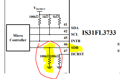
I did a much better job soldering the second board, but I ended up having the same problem as the first one, I could communicate with the chip over I2C, but I wasn't able to actually turn on any of the current sources even though I was getting all the correct responses back from my commands. I took this as an indication that it probably wasn't a problem with my connections since the chances of only connecting pins allowing me to get power and I2C to the chip but nothing else was probably not likely so I started scrutinizing each connection to see where I might have made a mistake.
It turns out that it wasn't exactly a mistake, but a combination of following the "Typical Application Circuit" and then not using it in that typical way.


If SDB is pulled low the chip will essentially shutdown everything other than I2C which was exactly what I was seeing. This is of course because in a typical setup with a micro controller you would pull SDB high when you wanted it to function, but otherwise it would shutdown to save power, but I was just connecting with the Bus Pirate to try it out and wasn't taking this into account.
I connected a bodge wire from SDB to the power source from the Bus Pirate and was able to successfully turn an LED on and change PWM settings, etc... The world makes sense again.
 Stephen Legge
Discussions
Become a Hackaday.io Member
Create an account to leave a comment. Already have an account? Log In.