HiFi audio codec module
A very small HiFi audio CODEC module
A very small HiFi audio CODEC module
To make the experience fit your profile, pick a username and tell us what interests you.
We found and based on your interests.
Hey pals,
check this out:
https://github.com/PaulStoffregen/Audio/pull/147
The code has been proprely merged in the Teensy Audio Library. Thanks to my project, the AK4558 is now officially supported by the Teensy Audio Library. Cool!
Cheers,
Mick
Hey there,
I had the time (thank you, Christmas holidays) to check thoroughly the issues I had in my previous update.
Let's start with the software issues:
I could not understand why the codec would not output anything even if I double checked the registers' configuration parameters until I put a function that reads their values AFTER I performed my I2C write operations: everything would read as 0 (zero). That was the moment when I grabbed my logic anaylizer and attached it to the I2C bus and found out the truth: I performed an out-of-bounds write when trying to write the Power Management register, meaning that every other operation performed on the bus after that one would not go well. In particular, when I was trying to write that register I put the CODEC I2C address instead of the Power Management register in the function (which is out of bounds).
Solved that, I noticed that my reads were off, that's because the CODEC keeps a counter of the last accessed register and would therefore return data from the last used address+1 and then wrap around to address 0; to fix that I just put a dummy write to the last register before reading the configuration.
This in turn lead to the discovery of another silly issue: I overwritten the Power Management register with the Mode Control register, therefore I was not turning on the power for the DAC and ADC. Damn copy+paste!
As soon as I fixed these, I got signals on the scope, but they were off....
Let's pass onto the hardware issues:
I ran the SineOutTest example you can find on Github to check if I got two sinewaves on the outputs, and they were there indeed! Only thing is that the left channel one was very low (like in "50 mV p-p VS 2.5 V p-p" low). I thought I misplaced the two resistors on the output; to check that I run a SPICE simulation of the output circuit w/ the inverted resistors and I had the same readings. I turned on the soldering station, grabbed some tweezers, and took them off the board, then I soldered them but it was still off... eventually I broke one of the SMD resistors and I therefore proceeded in hacking in a standard through-hole resistor from the output DC-blocking cap to the ROUT pin. The signals are now fine.
I also had shorted the input pins, but some solder wick solved that easily.
All in all, it now works as intented, here's the proof
This video shows the board running the SineOut test while attached to the scope......while this one shows the board running the sine test connected to a speaker, and then running the passthrough test, passing the signal received from my PC's line output (through a USB Audio interface) to a speaker.
I had a great time doing this, I actually always wanted to brew my very own HiFi Audio CODEC Module, and this was the perfect excuse to do so! I can't wait to do more and more stuff with this!
In fact, the reason why I put AVDD/AGND signals on the analog in/out connector is because I could piggyback expansion boards, here's a couple ideas:
Thanks @alpha_ninja for setting the #The Square Inch Project up, it was really fun to participate in this contest and it was really stimulating! You made me productive as hell.
Cheers,
Mick
Hey guys,
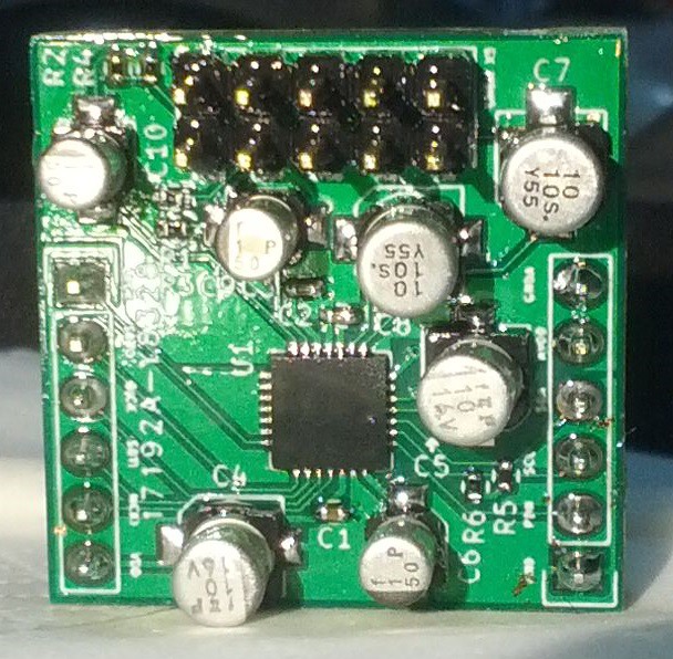
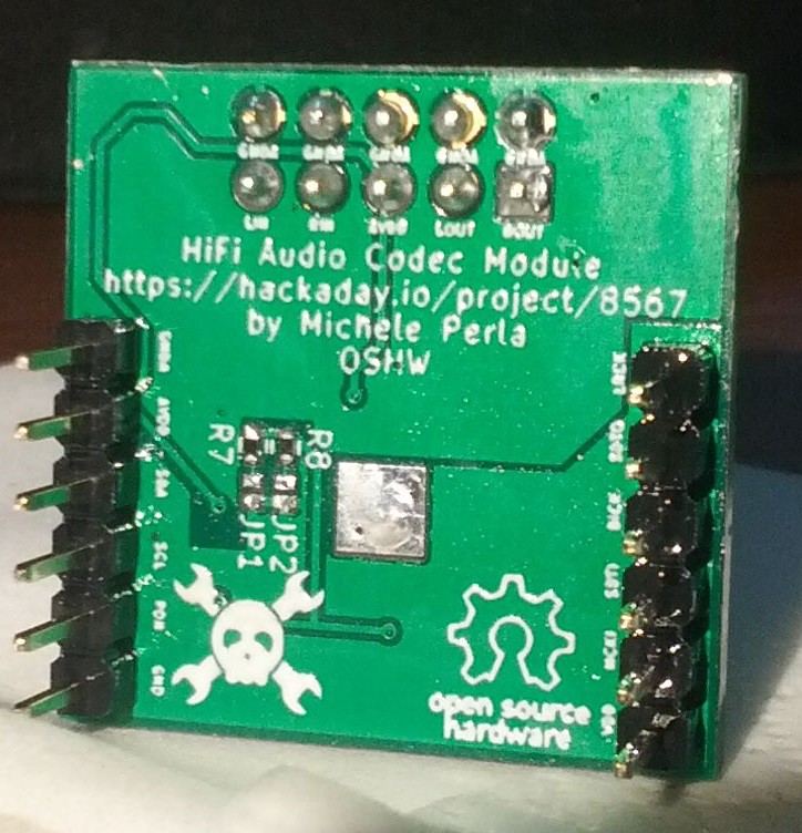
yesterday night I managed to build one prototype (at the cost of my sleep and mental sanity), here it is:
FRONT
BACK
Making this only left me 4 hours of sleep before going to work, and I was still nowhere near the end: I NEEDED CODE.
I spent all today making and testing a little add-on for the Teensy Audio Library (which I promptly forked) that lets you (read: me) control the module inside the Audio Library. Right now the AudioControlAK4558 class only has a working enable() method, an internal write() method to perform single register writes, and an internal readInitConfig() method that is run at power-up and copies all the default register values locally (in RAM) and also prints them on the Serial port. This allows us to:
1) Check if the chip is alive (if we receive all the correct default values, it is alive)
2) Edit the registers copy in RAM as you would with any AVR/ARM register (bit-wise operations) and then write them on the CODEC
I already mapped all registers (luckily there's only 10 of 'em) as well as all bit names so to easily perform such operations.
The "sanity test" is passed correctly (the Teensy 3.0 I'm using for the tests correctly read all registers) but there's something strange going on the MISO/MOSI lines; while the three clocks lines are all set properly, the MISO/SDTI and MOSI/SDTO lines show a 1.4circa MHz about 600 mV p/p , centered at 200ish mV above ground. The most strange thing is that the issue persists even if I detach the HiFi Audio CODEC Module and program the Teensy to a pre-existing Audio Library example using I2S (anyone using the SGTL5000 CODEC).
Here's a video for the lazy guys who don't want to read:
TL:DR:
I built one prototype, it powers up and works correctly but it does not output any sound due to some stange bug on the MISO/MOSI lines.
Conclusions:
I tried to stay within the 23.59 UCT limit set to today and I think I did it (after all, the module IS working), but the deadline has been postponed (woohoo) and I would have never left this bug unresolved anyway, because it makes the CODEC useless (no ins, no outs? no party).
Stay tuned.
Hi guys,
today is my long-awaited SOLDERING DAY! I received the PCBs last weekend and today I received all the components from DigiKey (the only international distributor that sells AKM parts, AFAIK)!
Here's the package:
Here's the content:
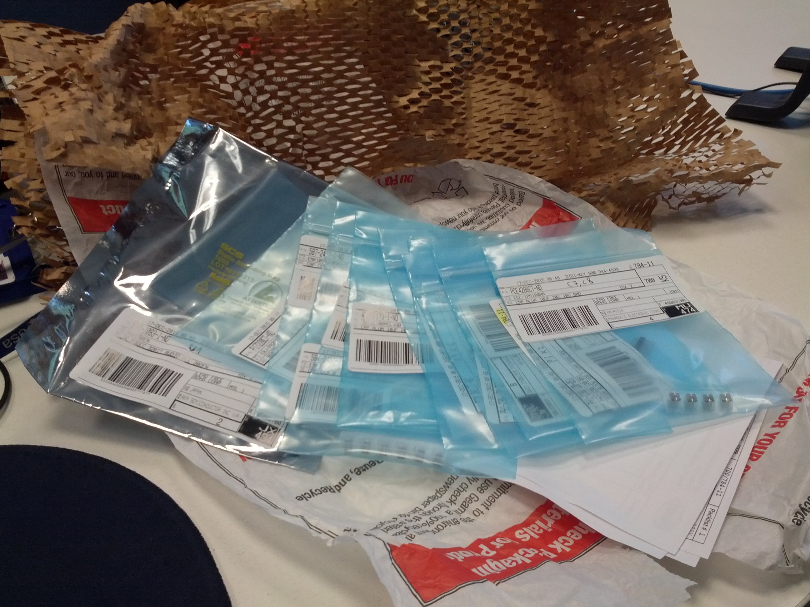
You may see that I already cataloged the bags with the names of the components name in the schematic/layout.
And here's the PCB:
FRONT
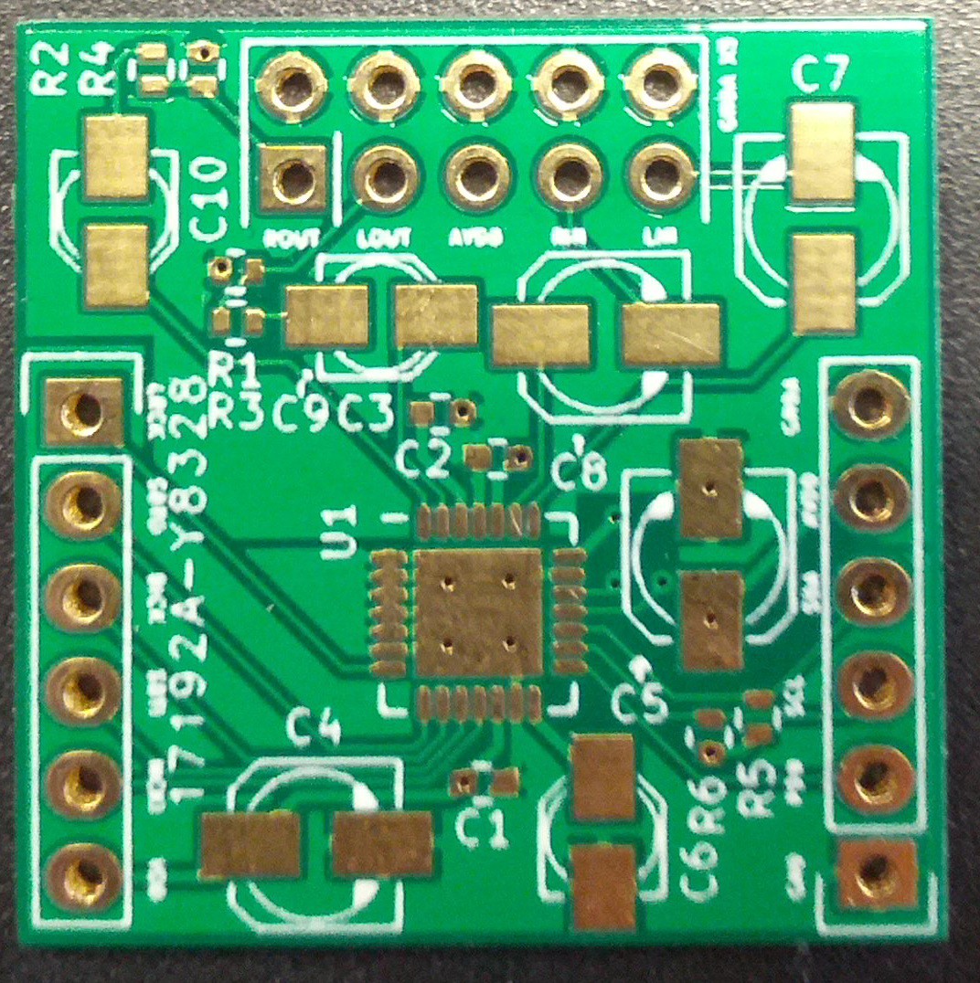
BACK
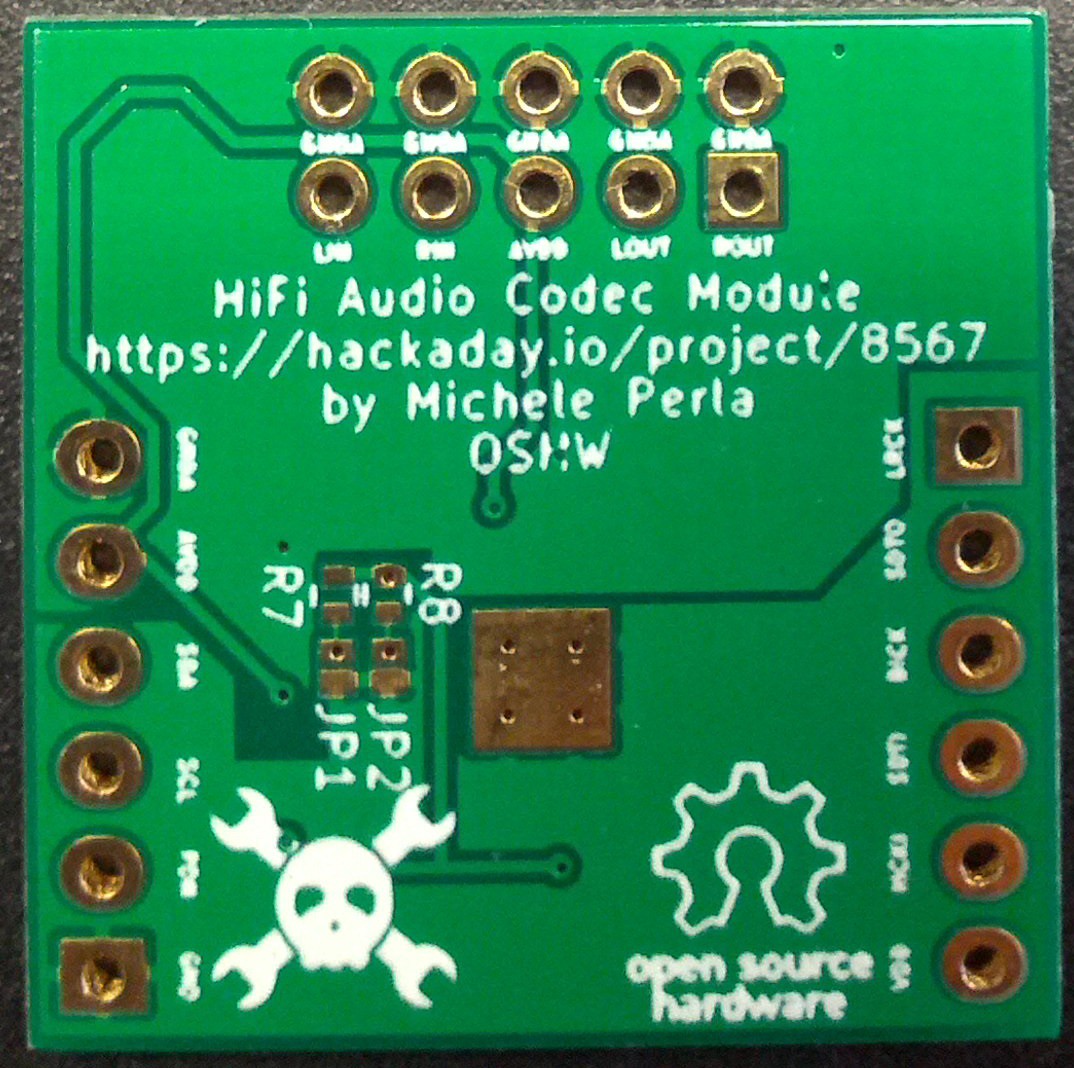
You can see that the text near the pinouts is too small, names like SDA/SCL are quite visible but some other that are more complicated (MCLK, BICK, etc) are not that readable.
I also made some little "mistakes"; I'd actually call them "components mis-selection" rather than mistakes. The thing is that I read on the interwebz that bipolarized capacitors are better for AC coupling audio applications, so I wanted to buy bipolarized aluminum electrolyic caps for inputs and outputs couplings.
I placed 4mm diameter 10 uF caps packages for the inputs, and 3mm diameter 1 uF caps packages for the outputs, but I could only find 5mm diameter 1 uF BIPOLAR caps, while I managed to find 4mm 10 uF bipolars. So, in the end, I'll use bipolar caps on the inputs and standard caps for the outputs. Next revision will host 5mm diameter caps on both inputs and outputs because the "audio grade" nichicon bipolar caps can be found in that size only.
Revision 2 TO DO list:
If I detect any error (I really hope not) after the first prototype has been built I'll report everything here.
I'll spend my free time at work to lay down an API to use the AK4558 with the Teensy Audio Library.
Stay tuned,
Mick
Hey there,
quick update to report that I just added the GitHub repository to the project page, so to be fully compliant with the rules of The Square Inch Project.
I finished packing the layout in a nice 1''x1'' board with only 2 layers for 4 (read FOUR!) power traces (digital power+ground, analog power+ground). SWEET! And, just in time for my holidays.
Now, off to Warsaw for a nice week of pre-Christmas holidays :)
Hey people,
quick update before the 1st December deadline: I added the finalized schematic + complete bill of materials.
So, good luck everyone!! It's layout time for me :D (will two layers be enough?)
Create an account to leave a comment. Already have an account? Log In.
Please make sure to upload photographic or video proof of this project working by the next deadline (in about two days!)
Thanks alpha_ninja for the reminder, I just received everything I need to build this proto. Check out the latest project log :)
Just a friendly reminder to please upload your complete design documents by 23:59 UTC on Dec 8, 2015 to be in the running for #The Square Inch Project!
This is your one-week reminder to upload design documents: https://hackaday.io/project/7813-the-square-inch-project/log/28566-design-deadline
Become a member to follow this project and never miss any updates
By using our website and services, you expressly agree to the placement of our performance, functionality, and advertising cookies. Learn More
Hello! I am interested about this shield , but first i tryed the one with SGTL chip from pjrc, so I did buil it but when the sharp waveforms are generated(like square, saw, pulse) i have some ringing
I don’t know if i will get the proper answer for this but does your AK chip shield has this issue or i did something wrong with my schematic build?
I am trying to build an osccilator buy the way. Waiting for your answer.
Lulu, Thanks!