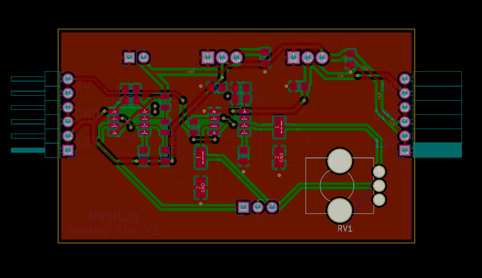
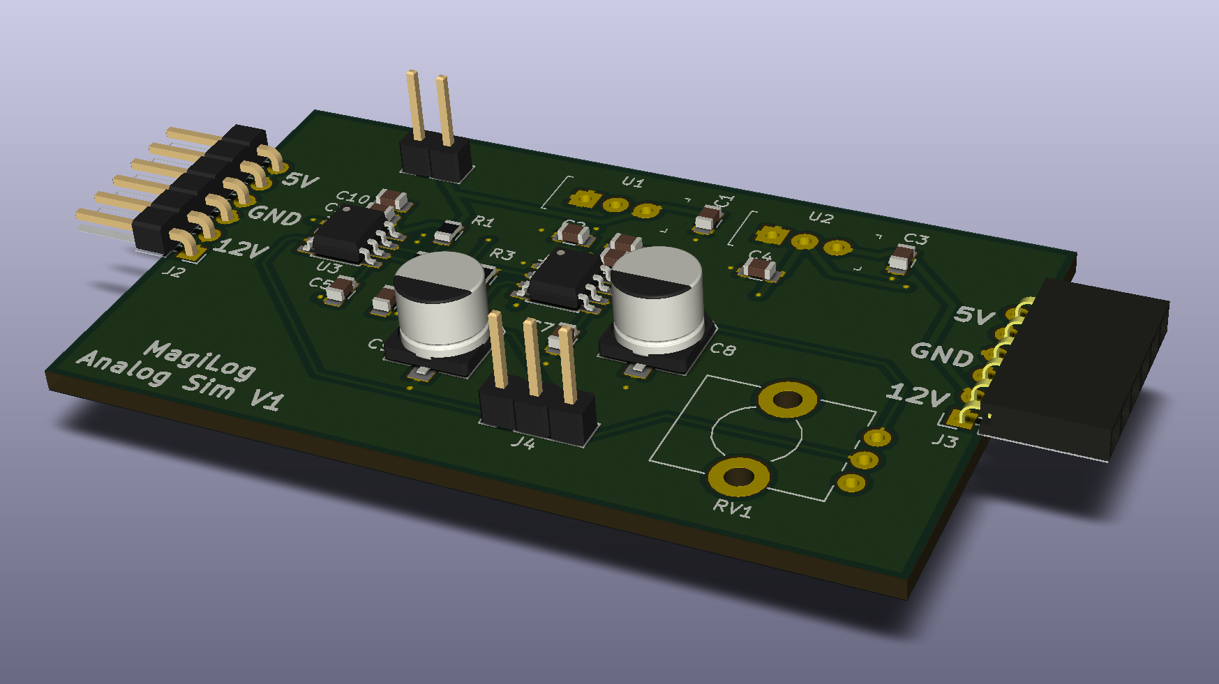
It’s been about a week since my last update and so far, I’d say I might be a little ahead of schedule. Pretty much done with refreshing my memory on Verilog and should be starting the analog module code tomorrow. I managed to finish the analog sim PCB a week early which is nice.

It’s a simple 1-sided 2-layer board with mostly SMD components. The pot, regulators, and headers are through hole due to availability/ease. I chose 0805 for the passives to make things easy to solder as space isn’t really a premium with this board.
From the original prototype there are a few changes. I’m now following LT’s recommended practices for decoupling the 555s. Also, the 555 that swings between the 15V and 12V rails has been switched to a LMC555 as it can handle 2-3V operation.

Last thing to do will be to do the Design Rules Check when I decide which PCB house to go with. Currently trying to decide between Seeed, OSHPark, and JLC. It's a small board so I'm leaning towards OSHPark due to the quality and low issue rate. Also, purple.
 Nigel
Nigel
Discussions
Become a Hackaday.io Member
Create an account to leave a comment. Already have an account? Log In.