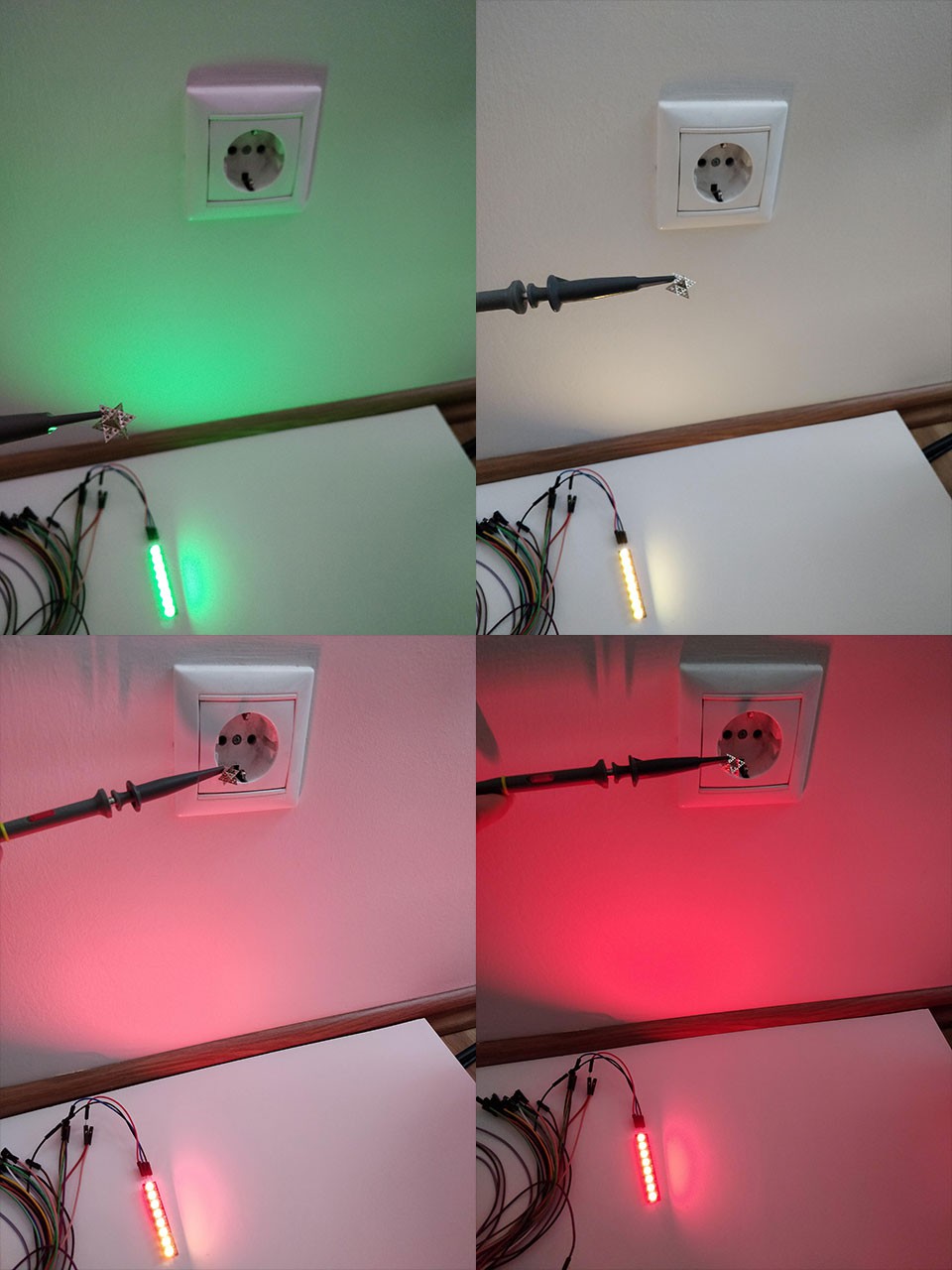
Venus-256 is a 256-channel data acquisition system (DAS) to provide a bio-potential reading in the 0.4Hz - 500kHz frequency range using a flat panel detector (FPD), displaying the processed data as an RGB-colored, hyperspectral image on a PC.
Requirements
The achieve the 0.4Hz - 500kHz frequency range we would need at least 1MSPS ADCs (because of the Nyquist-frequency). The electromagnetic fields we are going to measure are very week, so high SNR, high bitrate and low analog reference are needed. The SNR values for delta-sigma ADC are usually better than the SAR ADC, and also delta-sigmas usually have higher bitrate. Bi-polar input would be also good, because the field changes are independent from the device's power supply. So the ideal ADC is a 1MSPS 16-bit delta-sigma ADC with 1V reference and bi-polar input.
The lower end of the frequency range we need to measure is 0.4Hz. This means that ween need to store at least 1/0.4 seconds of data to be able to detect that frequency. This 2.5 seconds of data means 2.5 seconds * 16 bit/sample * 1M samples/second = 5 megabytes of data for every channel, so 1.28 gigabytes of RAM just for the raw ADC data. As a counter-measure we can define two sampling modes: low speed (1kSPS) and high speed (1MSPS). In the 1kSPS mode we can have the 0.4 Hz - 500 Hz and in the 1MSPS the 400 Hz - 500k Hz range, only using 5 kilobytes of ADC data/channel. This means that our RAM requirement is somewhat more than 5k * 256 = 1.28 megabytes for the ADC data.
Computations will be needed on all channels. Fast Fourier Transformation (FFT) would be ideal, but I don't think they are feasible, unless we use FPGAs or ASICs. As an alternative we can use an the Goertzel algorithm, which tells us how strong a signal is at a particular frequency. In order to be able to display a colorful, RGB image at the end, we need to have at least three Goerzel calculations per channel, ideally at least 50 times per second. The computation power estimation is more difficult and the use of an FPGA would help a lot.
The processed data should be transferred to the PC fast enough to have a solid user experience, so the refresh rate should be close to 50/seconds, and the latency should be lower then 100 milliseconds. If using three 8-bit Goertzels per channel, the estimated data rate should be in the 350-400 kbits/second range, which is easily handled by even USB 1.0 and potentially handled by Bluetooth Low Energy too (BLE 4.0 has 260 kbps and BLE 4.2 has 650 kbps maximum transfer rate).
In-system (in-situ) programming, firmware upgradability, USB or battery power source, .NET Core-based driver and API, WebSockets, Unity3D GUI, three-dimensional dual-tetrahedron or Sierpinski Gasket fractal antenna. Prepare for FPGA architecture and Raspberry Pi 3 B+ interfacing with Windows IoT Core.
Hardware Architecture
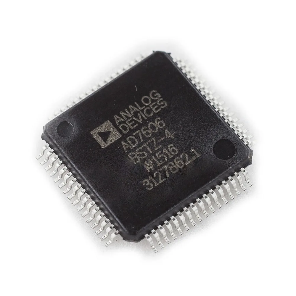
16x Analog Devices AD7616 16-Channel DAS with 16-Bit, bipolar input, dual simultaneous sampling 2x 1MSPS SAR ADC, 16-bit parallel output and 16+Mhz dual SPI output - 25 USD 4x Atmel ATSAME70Q21 MCU Cortex-M7 CPU @ 300Mhz, 384kB RAM, 480Mhz USB, 24x2 12bit 2MSPS SAR ADC, SD-CARD, 5xSPI - 16 USD 1x Raspberry Pi 3 Model B+ MPU Broadcom BCM2837B0, Cortex-A53 (ARMv8) 64-bit SoC @ 1.4GHz, 1GB LPDDR2 SDRAM, USB 2.0, Bluetooth 4.2, SD-CARD, 2xSPI - 35 USD
The AD7616 has two 1MSPS 16-bit ADCs (not delta-sigmas though) and it supports SPI output. This would mean that if we use just 2 sensors we can get 1MSPS and if we use all the 16 we are going to get 128kSPS. The analog low pass filters, the burst mode, the bipolar input and 2.5/4V internal reference support are also a plus. The ATSAME70Q21s should be able to handle up to 8 channels of SPI inputs with its five UARTs and three USARTs, it has just enough (384kbytes) RAM to store 5kbytes of raw ADC data per channel, which is enough to implement the 1MSPS/1kSPS decimated and the 300Mhz MCU should be fast enough...
Read more » Andras F

Nice :)