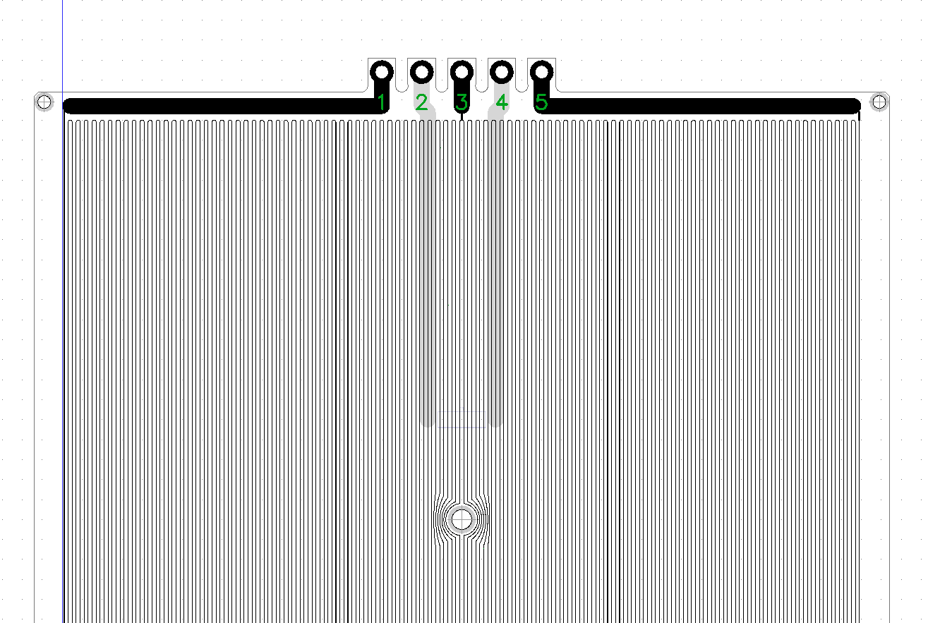
As mentioned, there are some safety concerns in heated beds no matter what voltage they are running on. I like the pragmatism of many RepRap builds out there, and I'm defenitely not safety fanatic, but I have the feeling that in terms of safety there is still room for improvement. The way some DIY printers are thrown together is actually pretty scary and we all know that the MTBF on these can be pretty low.
Overheating protection
With the intent to make this heated bed as safe as possible, what can we do? Adding a thermistor is a good idea, but what if it fails? What if the logic reading the thermistor fails. It might be a good idea to add another protection loop.
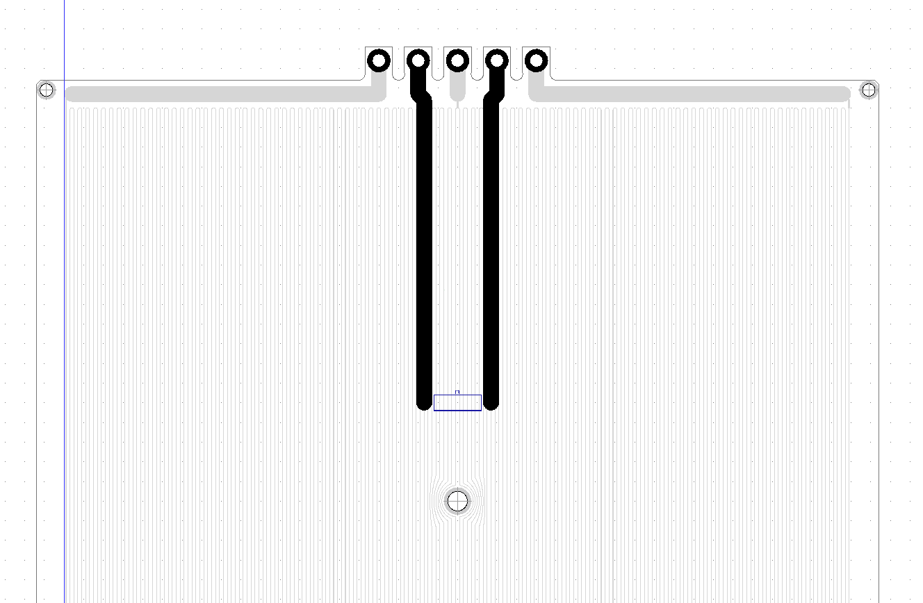
Below you can see the heated bed with two additional terminals, which a routed to a thermal fuse on the bottom side, close to the center of the heated bed. This way, you can still decide if and how you want to employ a thermal fuse.
The thermal fuse could also be implemented differently, i.e. just tapping it into the center of the heating trace, but then there would be two footprints required, one for 230 V~ and one for 110 V~ operation.


LED protection
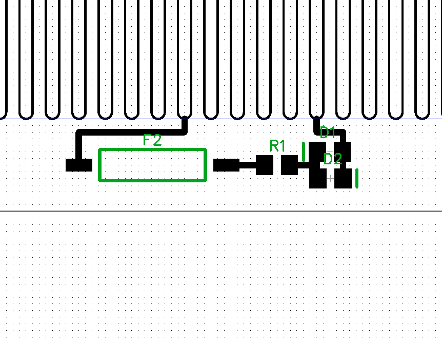
Another unsafe feature of the PCB in the current state is the vulnerability of the LED to faults in the section of the heater trace it feeds from. A open connection (like when the trace burns through) in this section would cause an increase in the voltage drop over the LED and its current limiting resistor. The current would also increase from 10 to 200 mA, which would probably blow both the LEDs plus the resistor. The only solution is employing a fuse, which just not so elegant as you can see in the picture below. I am not sure if this is actually necessary, because if there would actually be an open connection in the heater trace, the increased voltage and current will make the 0805 resistor pop right off, opening the circuit.

Overcurrent protection
Overcurrent protection is simple: Just add a fuse and feel safe. However, in the current design it's hard to employ a fuse that works for both 230 V~ and 110 V~. Since this was already a problem with the thermal fuse, I'm considering to just make two different designs, one for 230 V~ and one for 110 V~. Also, through hole components (like most fuse holders) are not allowed, since the PCB must remain flush on one side. Since there is no necessity to have the current fuse onboard, I chose to leave it to a cable fuse holder.
 Moritz Walter
Discussions
Become a Hackaday.io Member
Create an account to leave a comment. Already have an account? Log In.