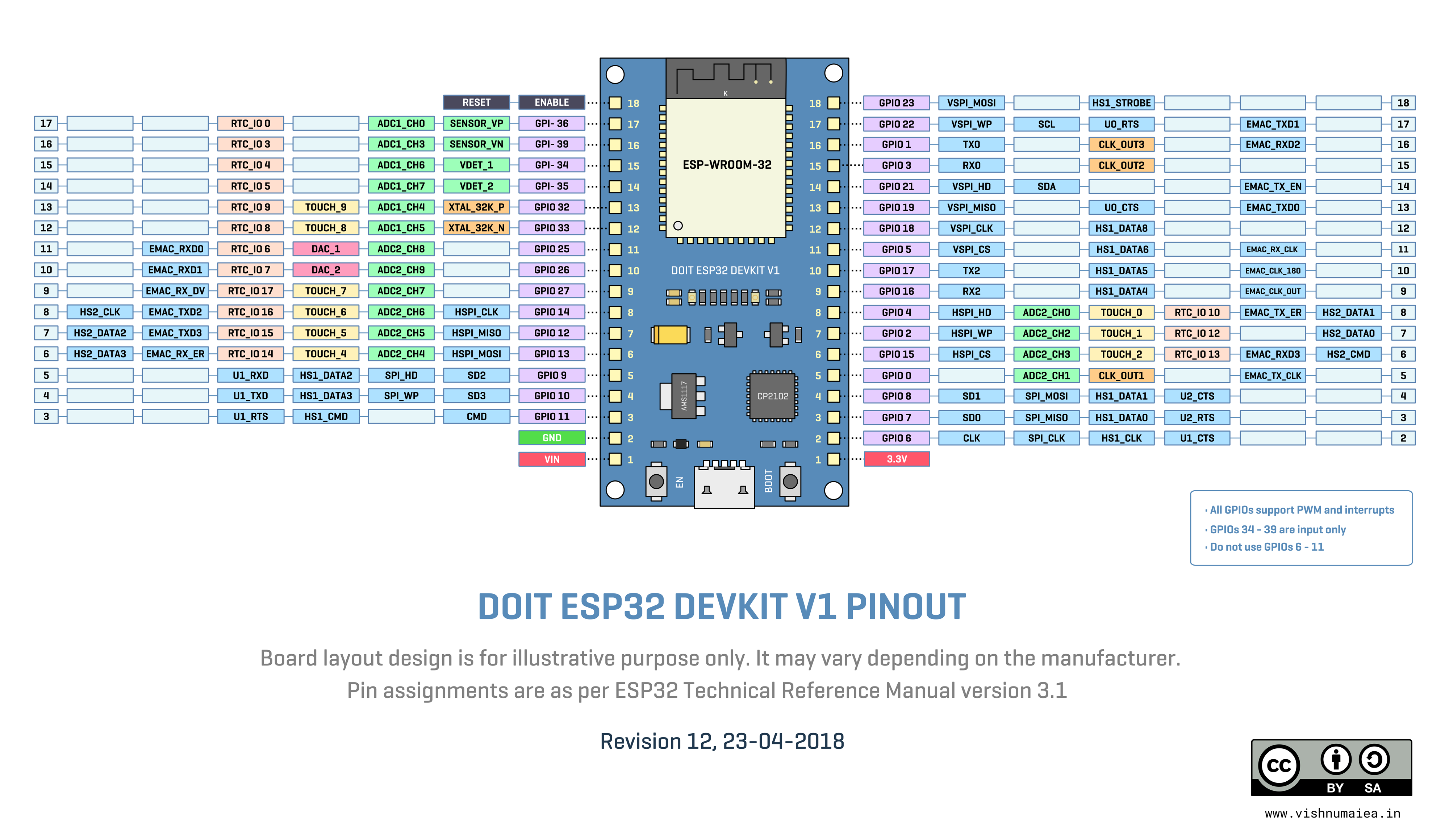
ESP32 is a feature packed power house when it come to price-performance ratio which makes it ideal for all IoT applications. But there's one tiny drawback - limited number of GPIO pins. On the ESP-WROOM32 module, some pins are used by the flash chip and can't be used for other purposes. Some other set of pins can only be used as inputs, not outputs. As per the datasheet, ESP32 has 34 GPIOs of which I/O GPIO pads are 0-19, 21-23, 25-27, 32-39, while the output GPIOs are 0-19, 21-23, 25-27, 32-33. GPIO pads 34-39 are input-only. So in total we get 22 I/O pins and 4 input only pins.
Even though it is not apparent in this initial phase of the project, sooner or later we're going to run out of pins if we're going to add more sensors and stuff in future. That's why I'm considering adding a less powerful but GPIO rich coprocessor to the design. The second processor or microcontroller could offload some tasks from the ESP32 chip giving us more room for some possible number crunching tasks. For that I'm considering the AVR Xmega series ATxmega128A3U which has 50 IO pins (64 pin package) which is plenty. It runs at 32MHz, has 128KB flash, 8KB SRAM, 7 UART, 10 SPI, 2 I2C and one USB modules.
Let's estimate the pin requirements for each interfaces.
- SD card - 4 (hardware SPI)
- Display - 4 (3 wire SPI with MOSI only and CD)
- I2C for sensors - 2
- GPS - 2 (hardware or software UART interface)
- USB to Serial - 2 (software of hardware UART)
- LoRa module - 4 (hardware SPI)
- Keypad controller interrupt - 1
So that's 19 of available 26 pins and we still have 7 pins left. If we ever use up all the pins left, we'll have to add a coprocessor.
 Vishnu Mohanan
Discussions
Become a Hackaday.io Member
Create an account to leave a comment. Already have an account? Log In.