-
Some info on interfacing with the HP45
09/25/2018 at 19:13 • 0 commentsIn the previous logs I have barely mentioned the interfacing with the HP45, although it is quite an important part of this project. The best I did was this log, where I spent 62 words on the problem. In this log I will give some more background on what the problem with the HP45 is and how to work with it.
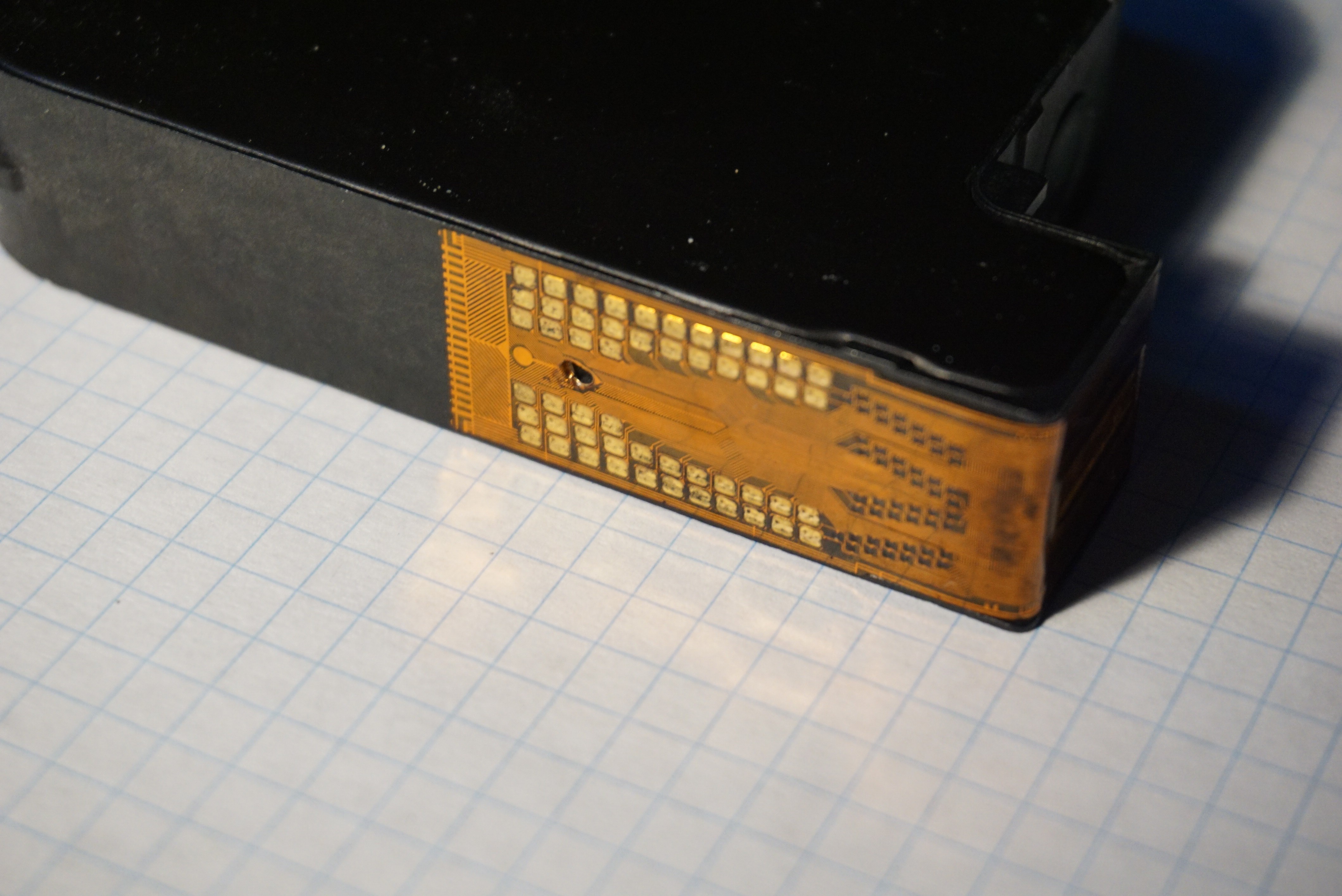
Too many pads When you look at it the problem is quite simple. The HP45 has too many pads. Reliably connecting to 2 or 3 pads is simple. Reliably connecting to 52 is a bit more difficult. Depending on what pad you lose, you can lose between 14 and 22 nozzles. The problem with this many pads is so big most manufacturers don't bother with it anymore. They just put some more electronics in the printhead itself. The HP45 is between the first inkjet printheads where they were figuring it out, and the later printheads where they optimized the design.
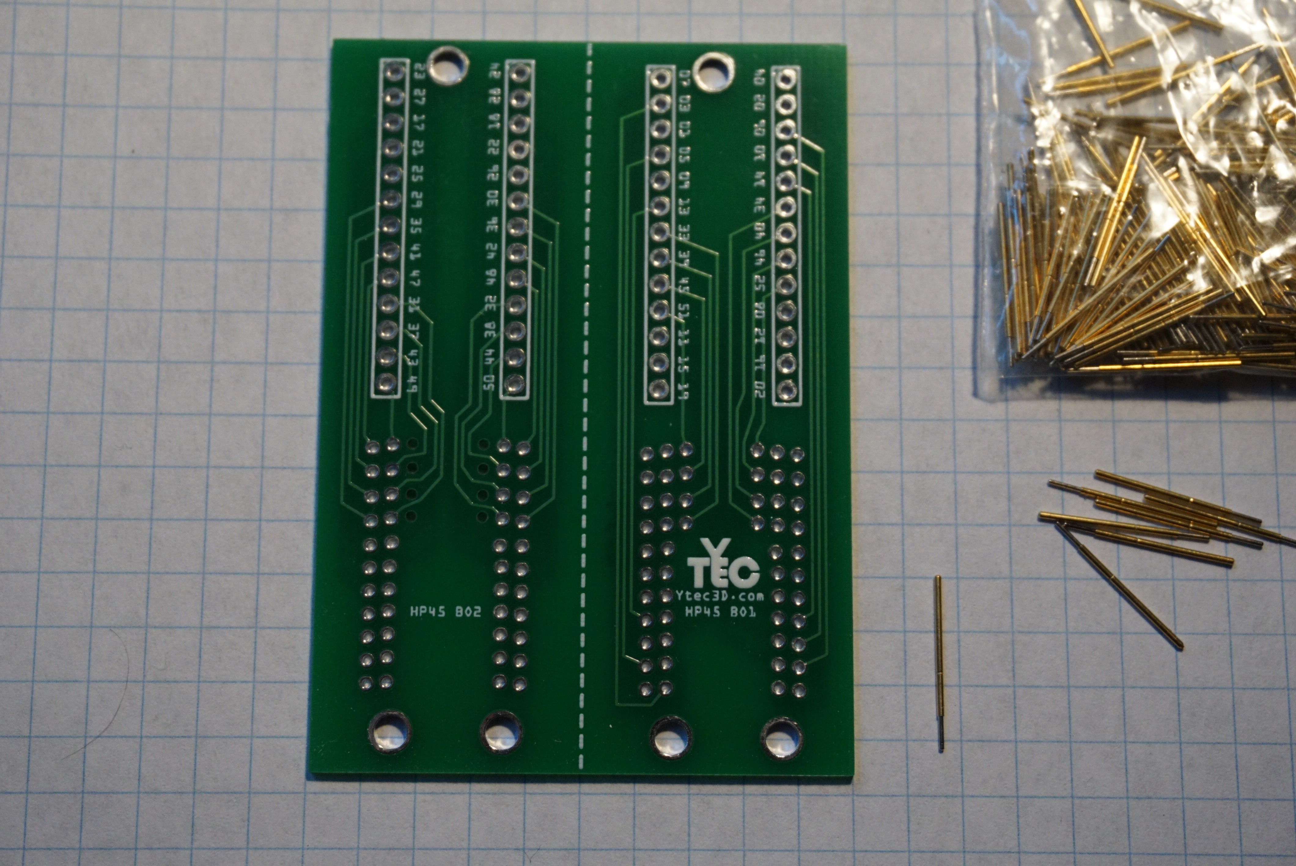
Pogo pin connector
Pogo pin breakout board (on 5mm squares) ![]()
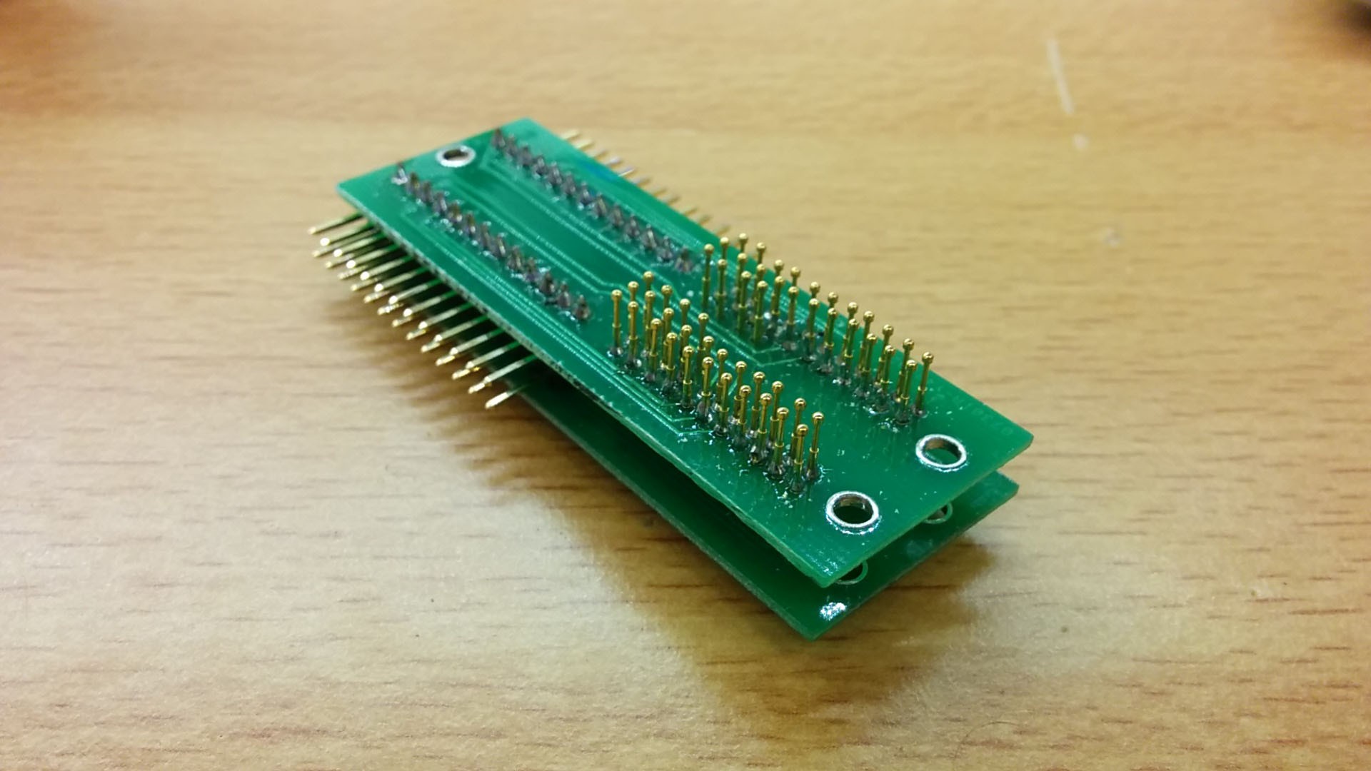
Imagine replacing a pin on this (I did, it sucks) ![]()
This is 2 PCB's, with IC's in the middle. If something breaks, good luck fixing it.. My first way of connecting to the HP45 is with a pogo pin board. I have had breakouts and full drivers built this way. They are built on 2 boards to give the pins stability and to make routing somewhat possible with a 2 layer board. It is practically impossible to route without more than 2 layers, because all pogo pins are essentially through hole, and you cannot reach all the pins at once.
In all fairness, it worked quite well. It is not perfect though. The pogo pins are only 0.8mm thick and so are incredibly fragile. In most printhead carriers you inert the printhead from the top. This means it is easy to hit the pins sideways while loading a printhead. This has happened, and the pins cannot take any sideways load and simply bent. The pins are soldered to both boards, so if a pin gets bent, you have to desolder it from both boards at the same time. I have done this, but it is the absolute worst job to do.
Cue the HP45 connector
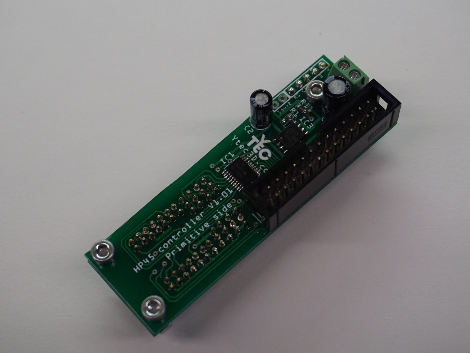
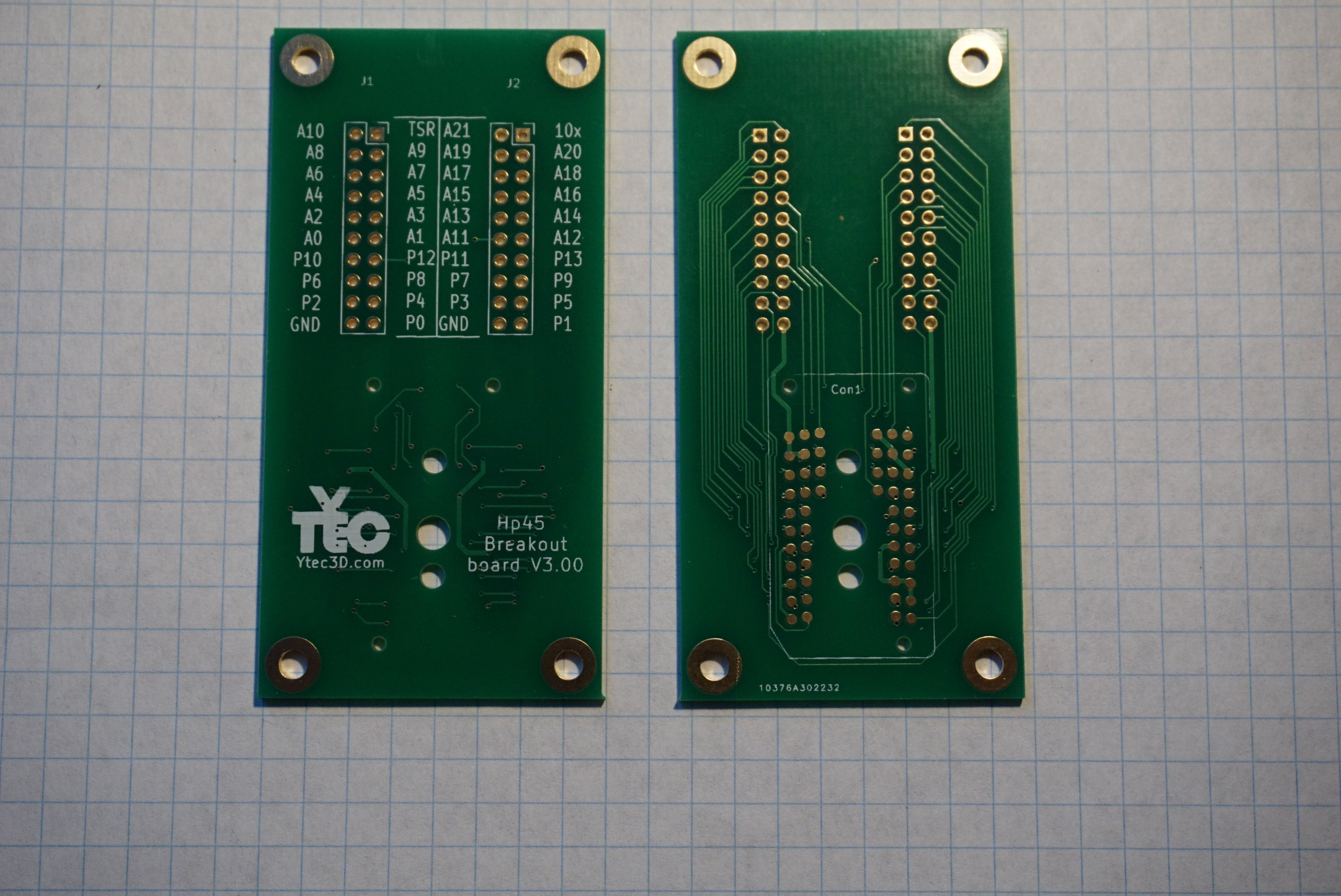
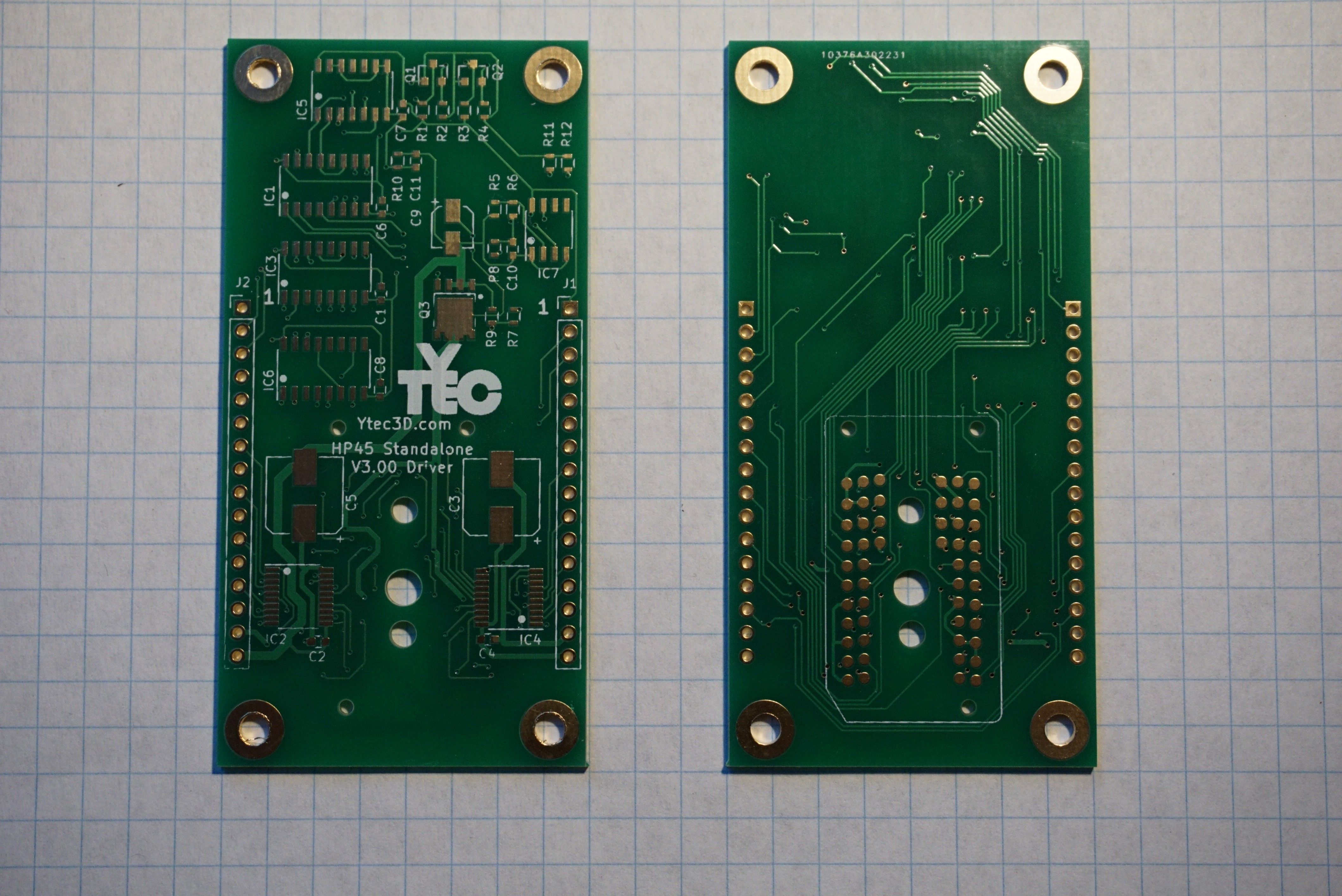
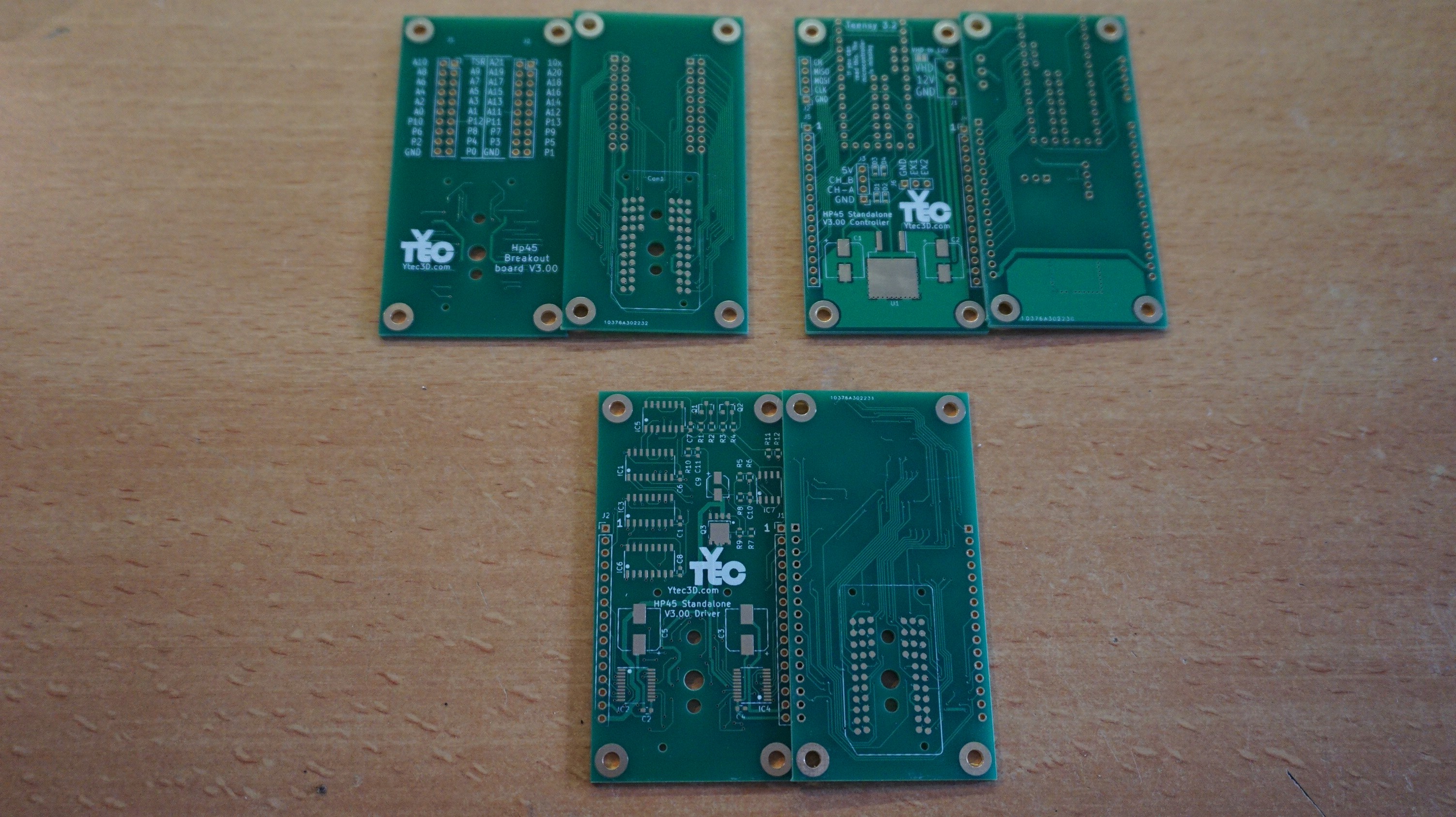
Breakout board Full driver board Fabulous, isn't it?
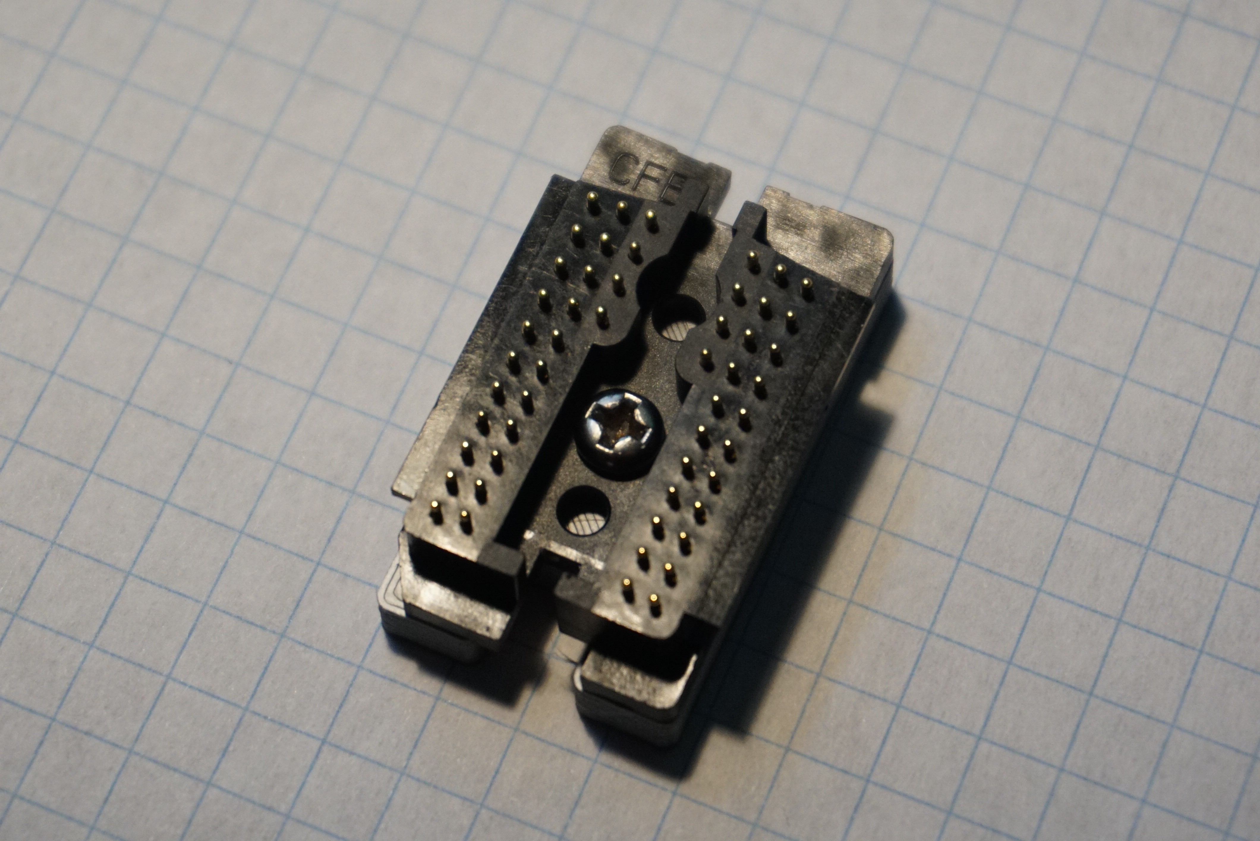
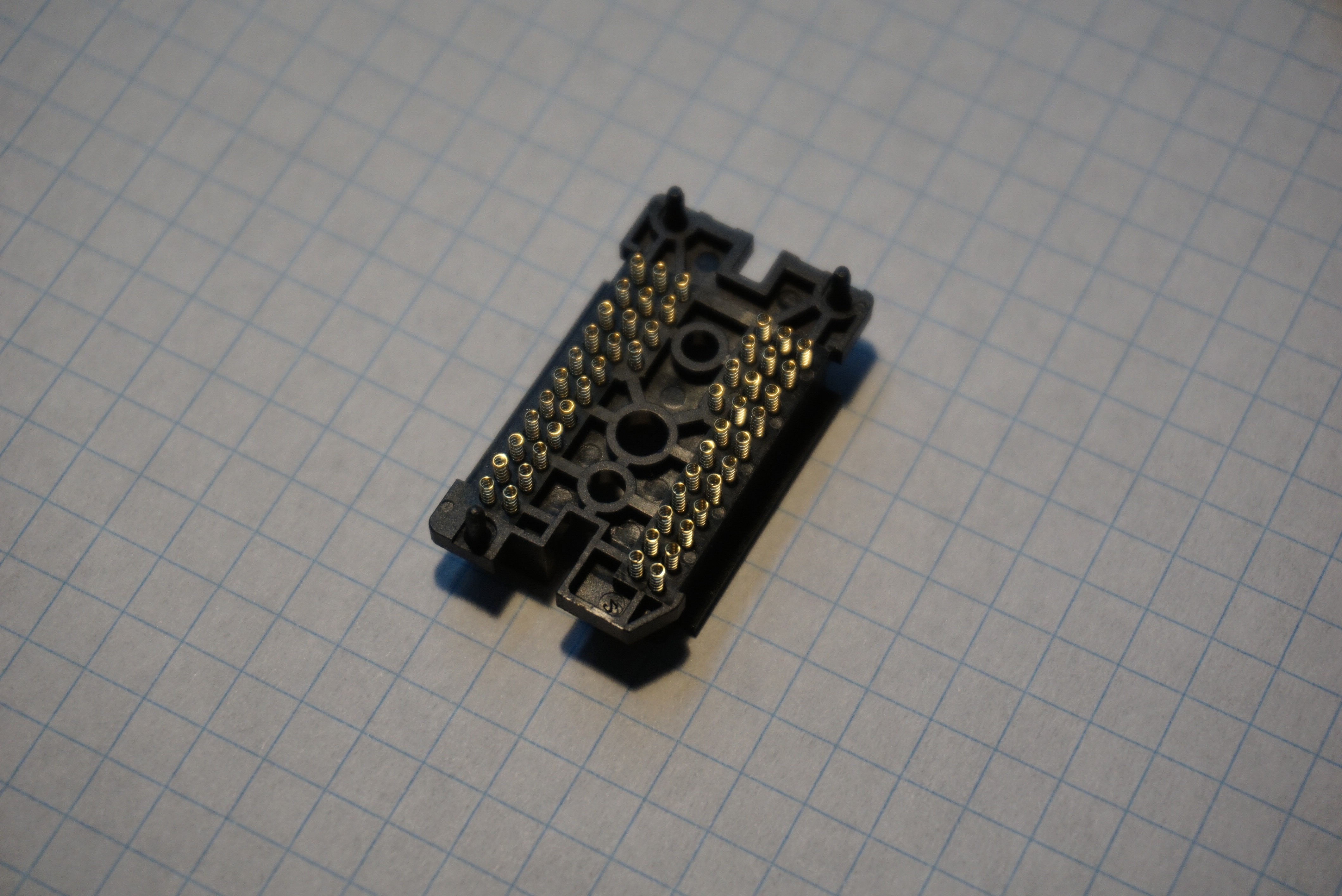
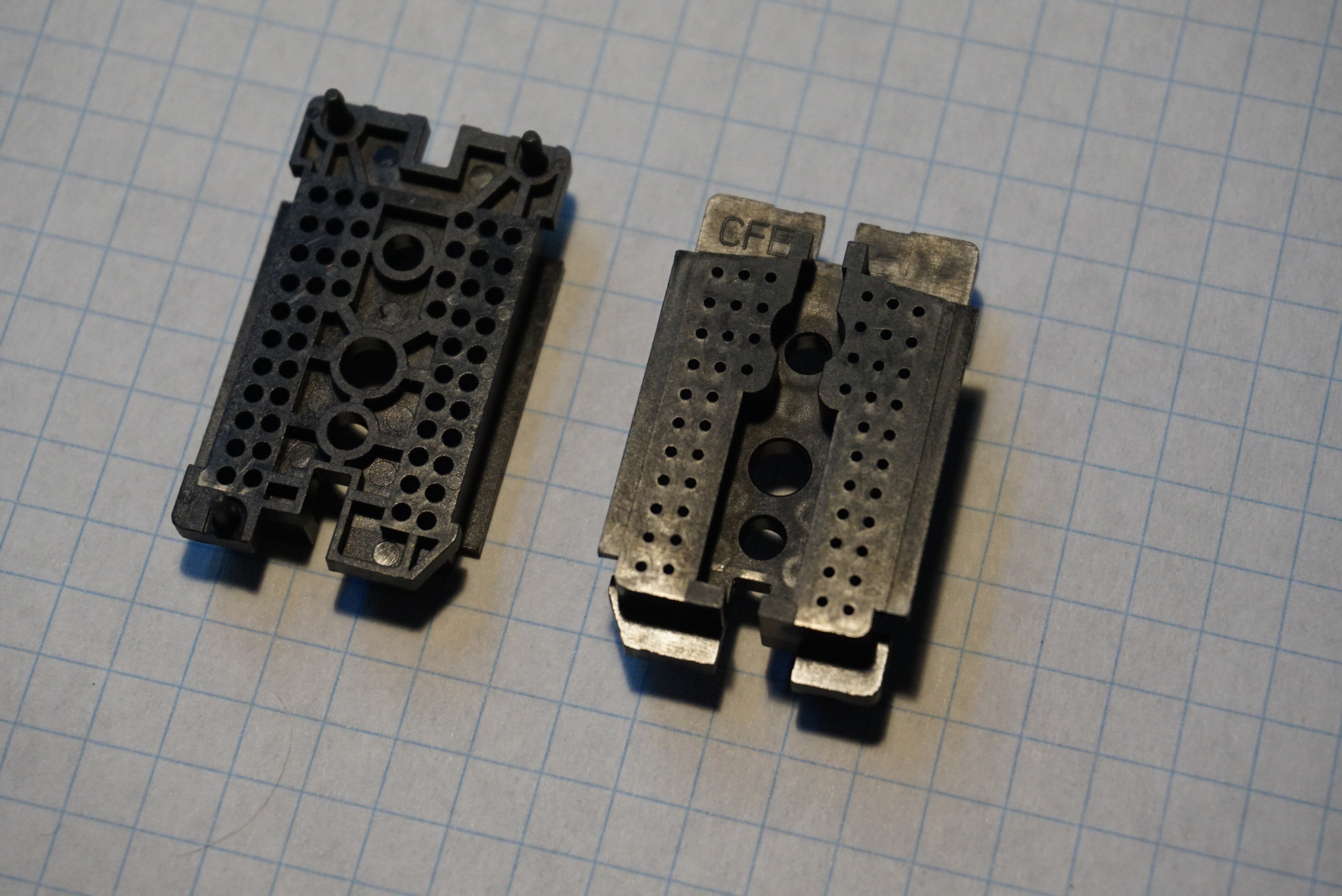
The HP45 connector is a purpose built connector that has 52 pogo pins in a single plastic housing. It does not have the travel of my own pogo pin circuit (not that you need it), but it has pins that you can hit sideways without breaking them. Also it does not solder in place, but makes contact with the PCB pads, giving more freedom in routing. In my case I can now route on a single 2 sided PCB.
The HP45 connector is founds here: https://www.cfconn.com/product-show_14712/. It is also on Alibaba through the same supplier. While it states it can supply small quantities for under $10, my experience is that those prices start happening at size 100. You get these connectors unassembled, dropping an assembled one is cause for much tears.
I myself have bought a batch at CFConn. I now have way to many. I sell them on Tindie right now. I will start selling more HP45 related components later when the documentation is finished.
https://www.tindie.com/products/Dragonator/hp45-printhead-connector/
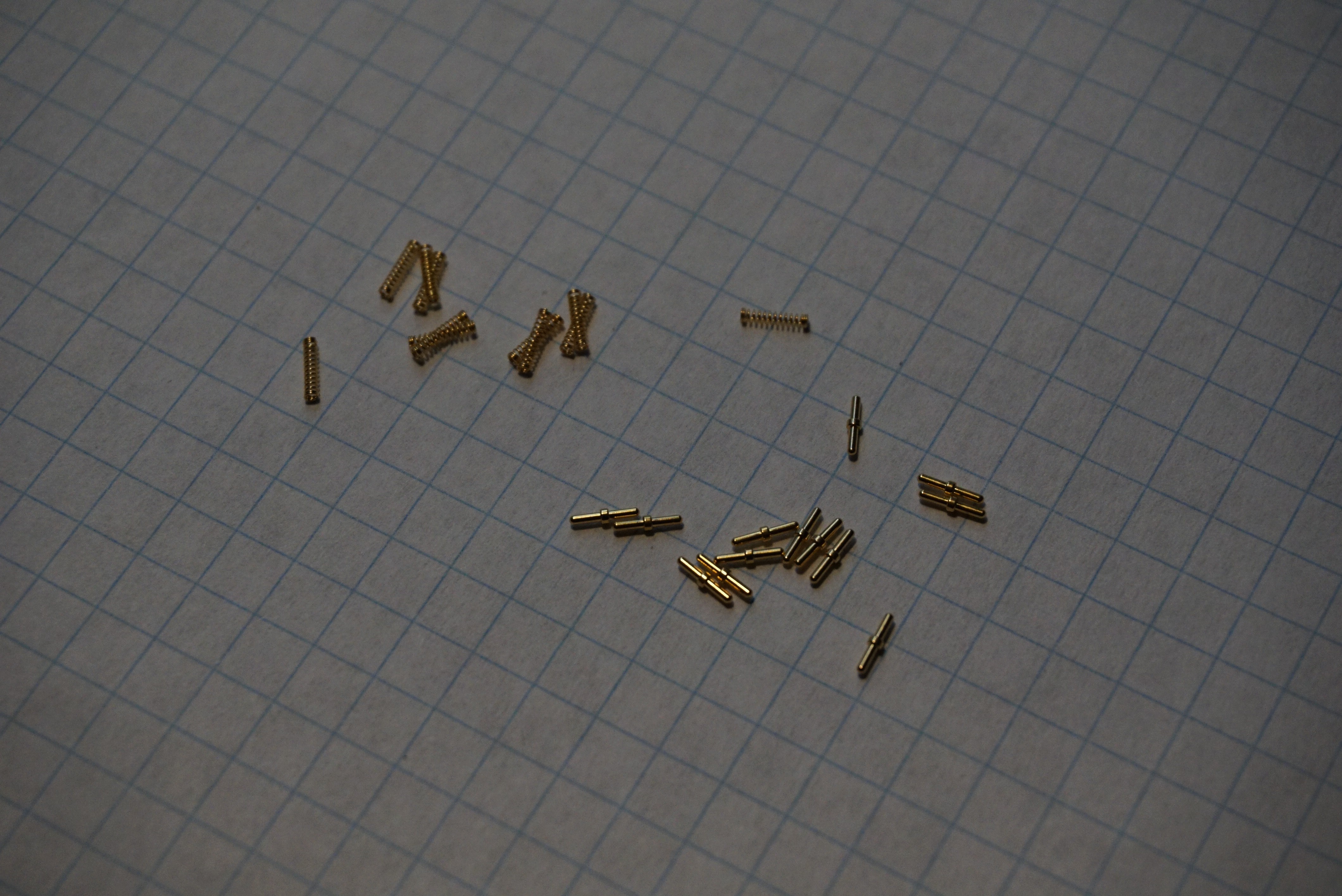
The HP45 connector uses tiny gold plated springs and pins in a plastic housing to make connection to the HP45. The travel is about 1.5mm on each pin.
3 locating pins locate the connector to the PCB. 3 holes can be used to mount the connector. the 2 outer holes are 2.8mm, the inner hole is 3.85mm. I use the 2 outer holes with M3 cutting into the holes, but I am still looking for proper plastic screws. To make a connection with this printhead, you'll need 52 located pads on a (preferably gold plated) PCB. I have included the KiCAD files on the page of the connector, here on my own site, or is in the electronics section of the source files.
I currently have 2 boards, a breakout board that breaks the 52 pins out to 2 2x10 pin boxed headers (grounds are shared) and 1 driver board. The driver board also needs a controller to work, which is a separate board stacked on the driver board through 2 headers.
Carriage
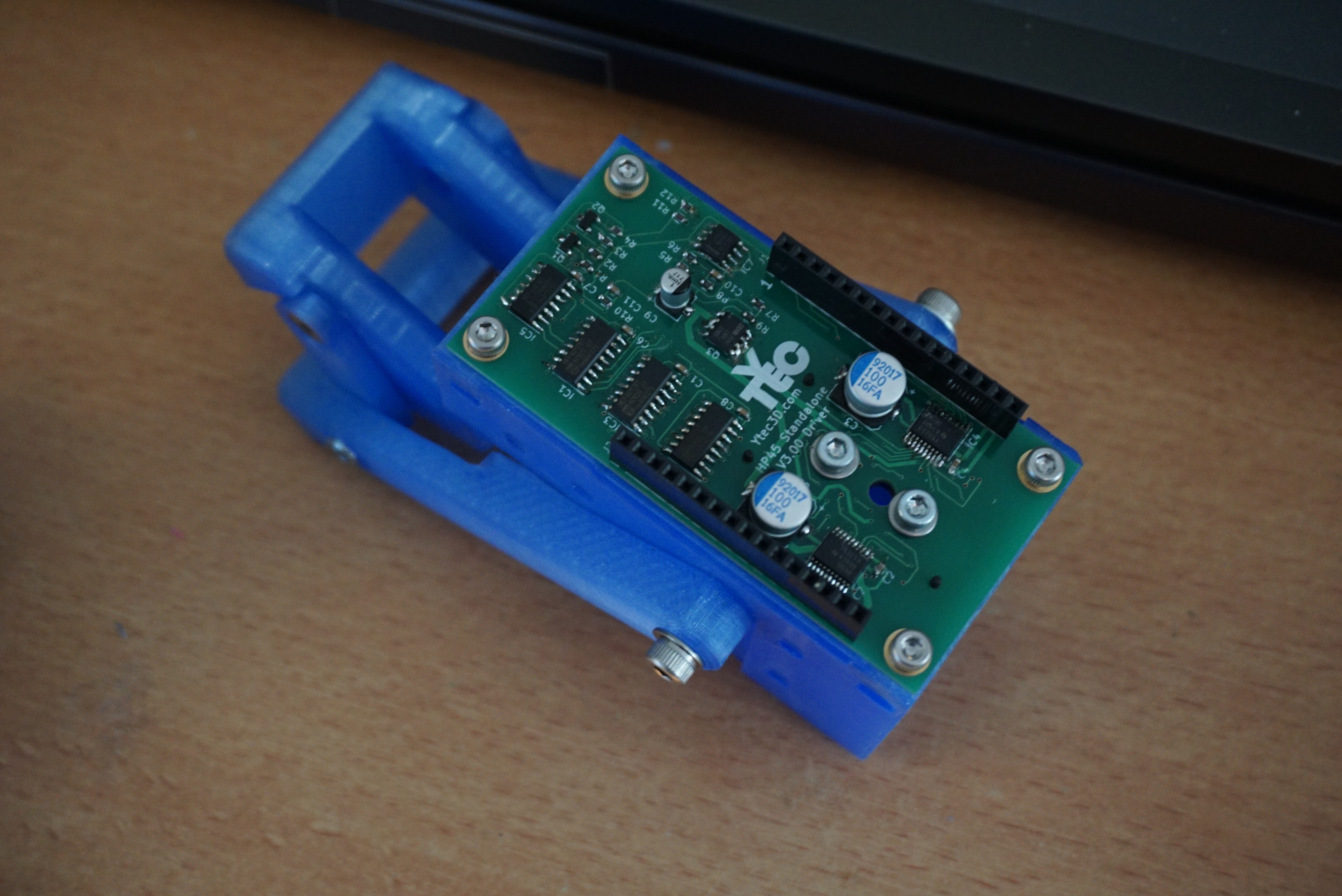
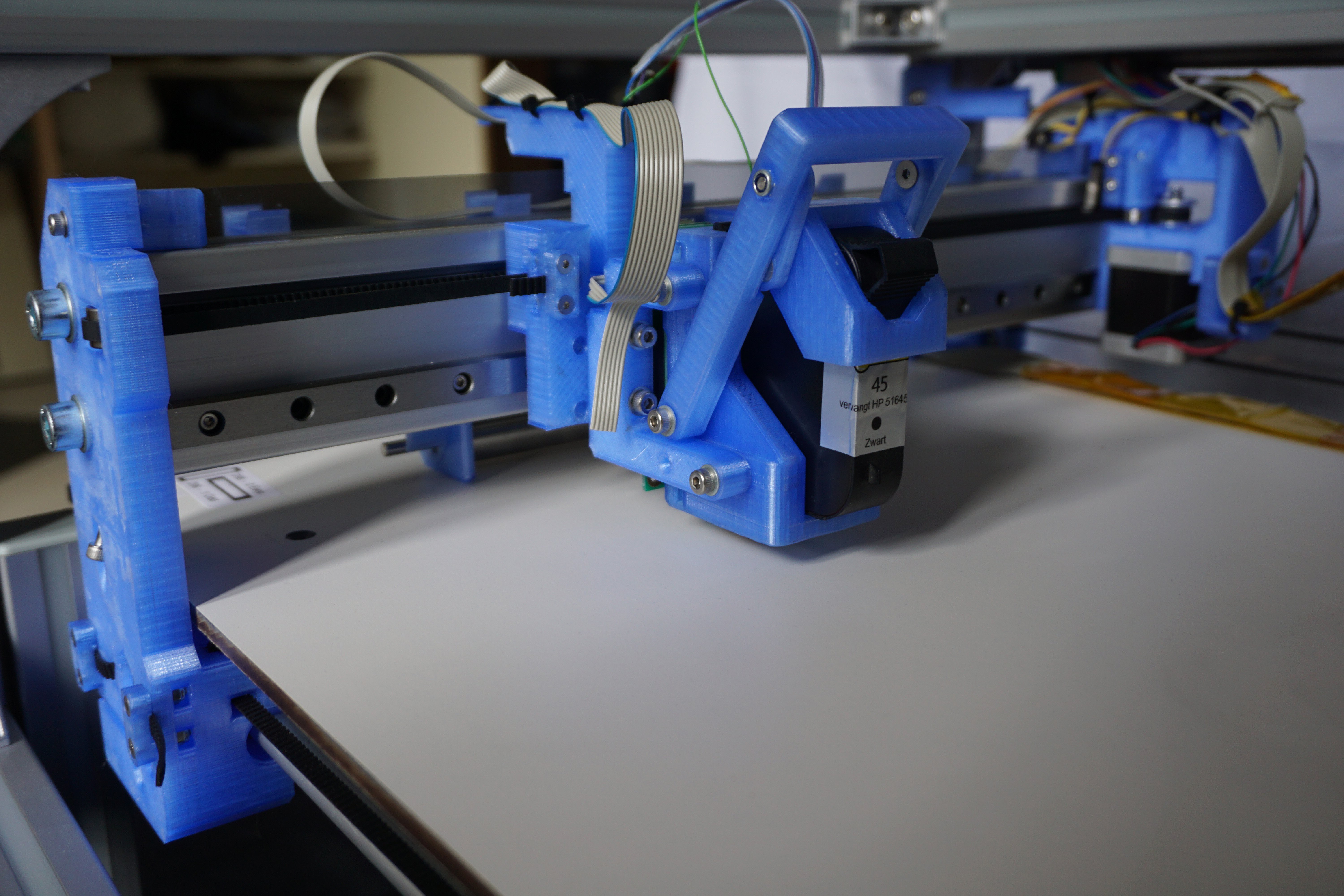
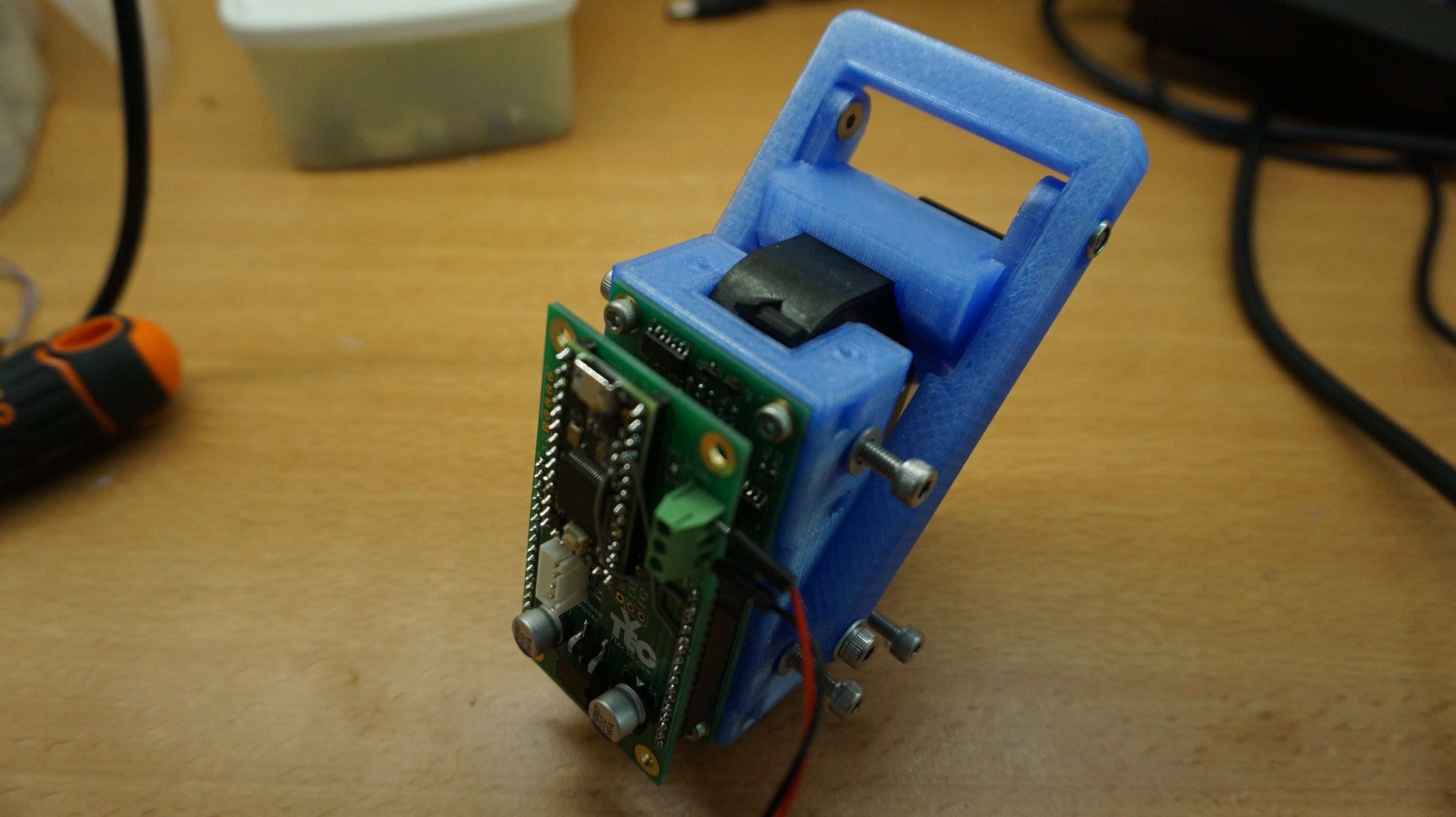
The carriage holds the HP45 controller, and deserves a bit more attention on its own. It is a part that should be very usable on it's own. I will order more components and make an assembly guide for the whole printhead on it's own with another set of parts. Can't promise when, it might take a few weeks, but I will. Remind me if I forget.
-
She prints!
09/24/2018 at 18:51 • 0 commentsNot much, not amazing, but prints nonetheless.
I have made all modifications to 3D print in the last few weeks. Now all I need is to try out more, and make the improvements to make it better. Currently I am printing in original Zcorp powder with HP45 ink. I got this powder (and binder) from a friend a few years ago. I have yet to experiment with my own powders and have only tested with this so far. I printed a 12mm diameter by 3mm disk as a proof of concept. The part was strong enough for removal and cleaning.
There are a few limitations at this moment. I have not yet had the time to modify printheads. This means I am printing in pure ink. This means that 1. my print is extremely black and 2. the green strength (untreated part strength) is poor. The powder has a lot of chunks, hairs and other contaminants in it. I still need to filter it through a mesh some time. I have to use the depowdering tools I made for Plan B (http://ytec3d.com/depowdering-station/). I have no good superglue anymore to infiltrate the parts, so I have no pictures of finished parts. The part broke while infiltrating with bad superglue.
Those are all the tiny problems left. I can easily fix them with some time though, so it is all right.
Pistons and new layer
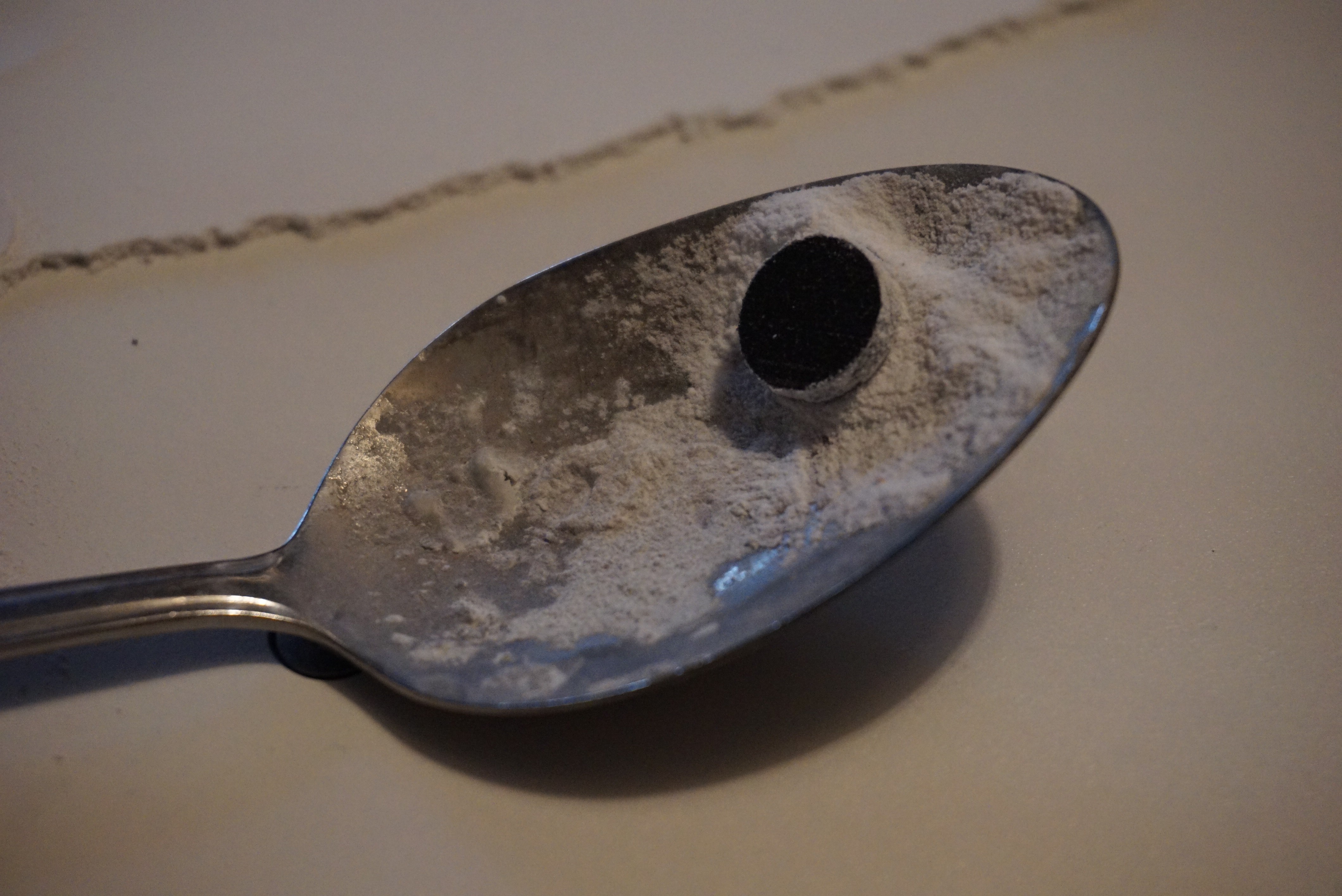
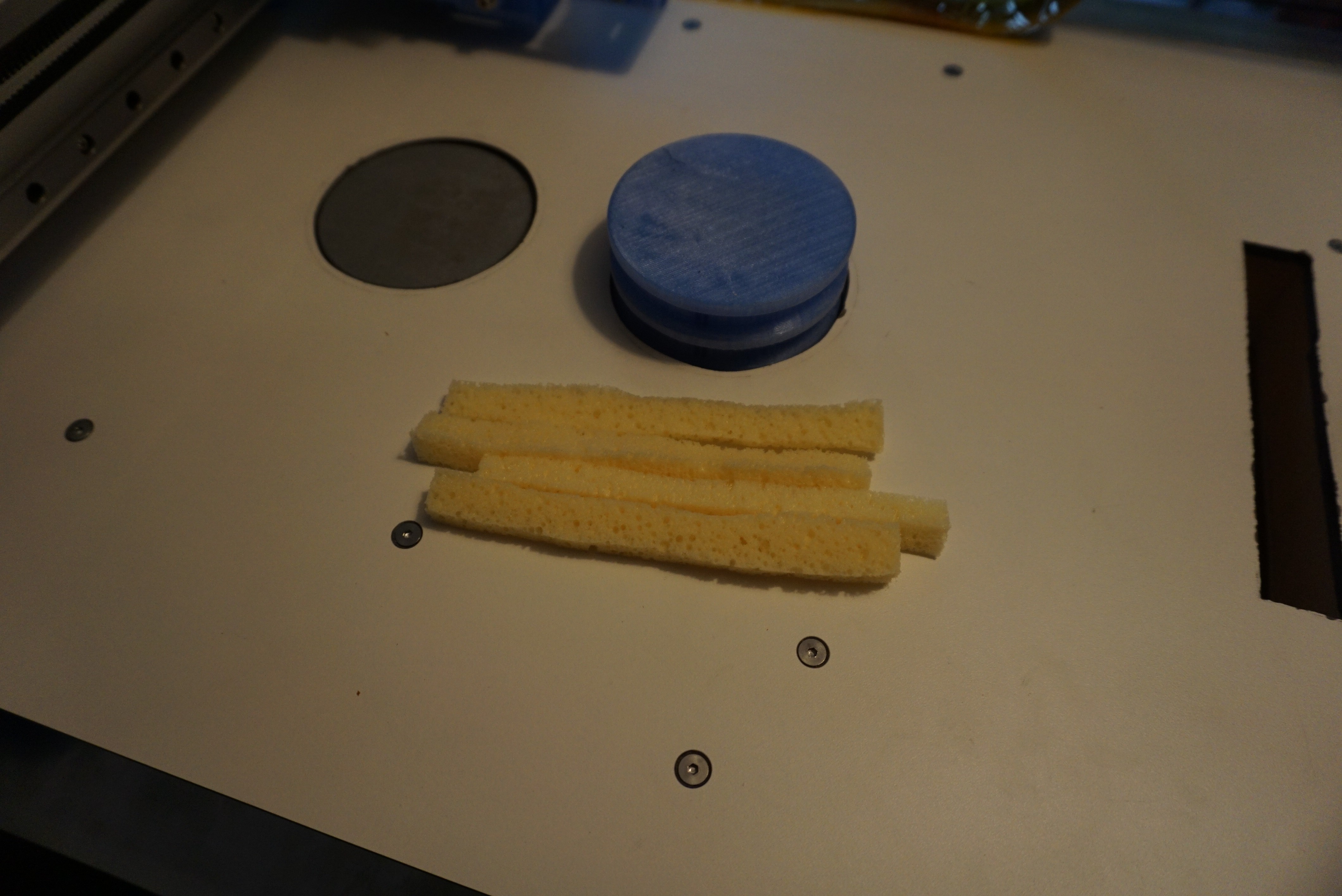
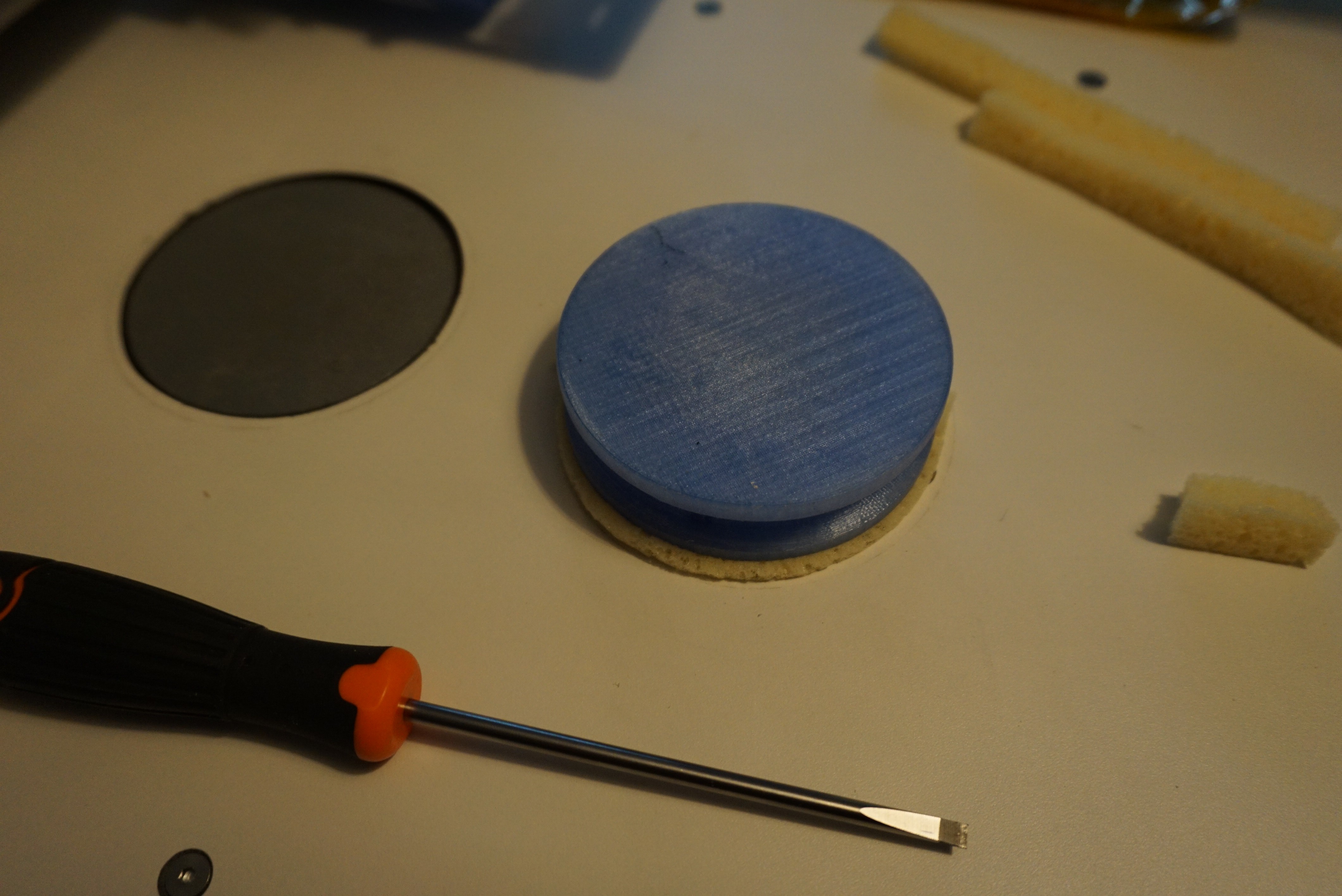
The pistons now have seals in them. I have used sponge for a while because it is low friction and flexible. I have a little leak on the feed piston to fix, but other than that it is powdertight.
While preparing to print, I made some final tweaks to the new layer function. I have made it so the last motion is always up. Even on movements down it will now move down too far, and back up again. This is to ensure accuracy. By always moving in the same direction you prevent the backlash in the leadscrew causing problems. I cannot move both pistons at the same time due to GRBL 4th axis issues, so moving pistons is not terribly fast.
The current sequence is:
- Move to the back of the feed piston*;
- raise the feed, lower the build;
- starts spreader and move to overshoot position;
- stop spreader, move pistons down by clearance distance*.
(*all piston movements will go down first so they always move up)
Cover
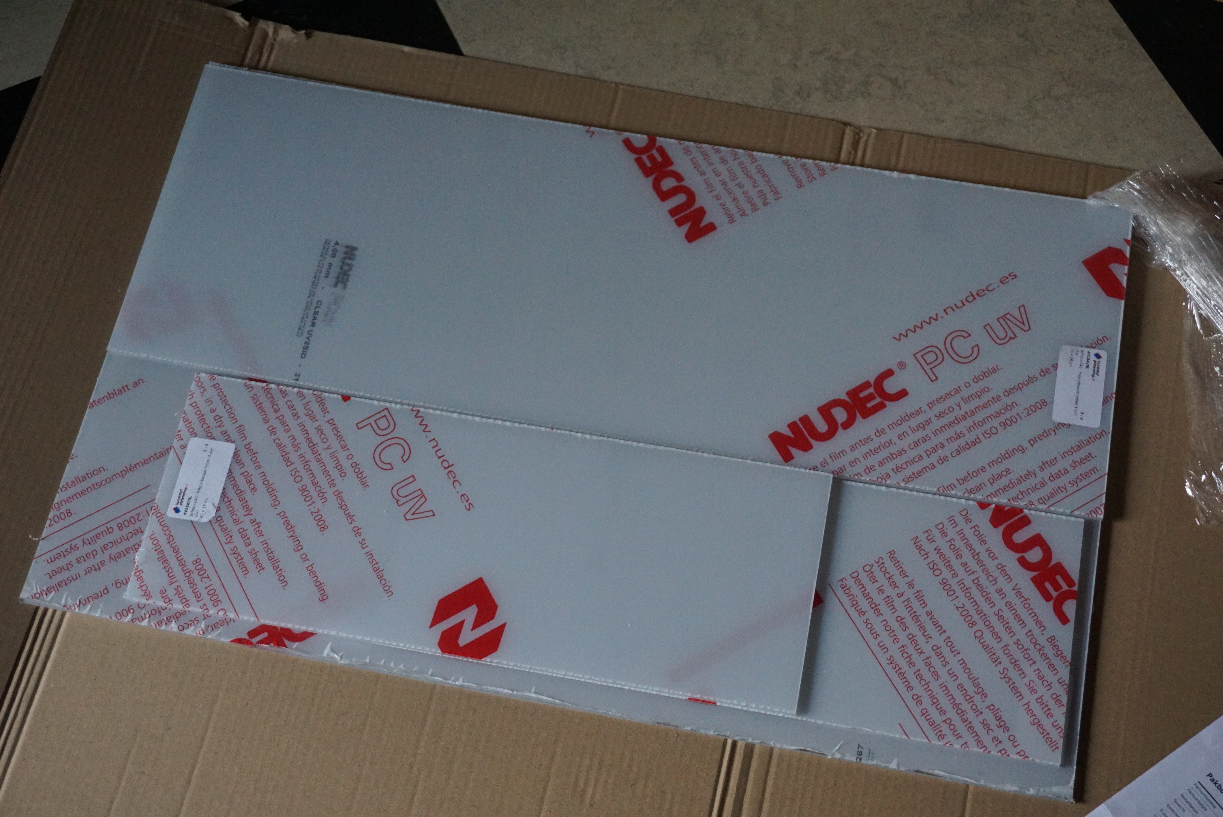
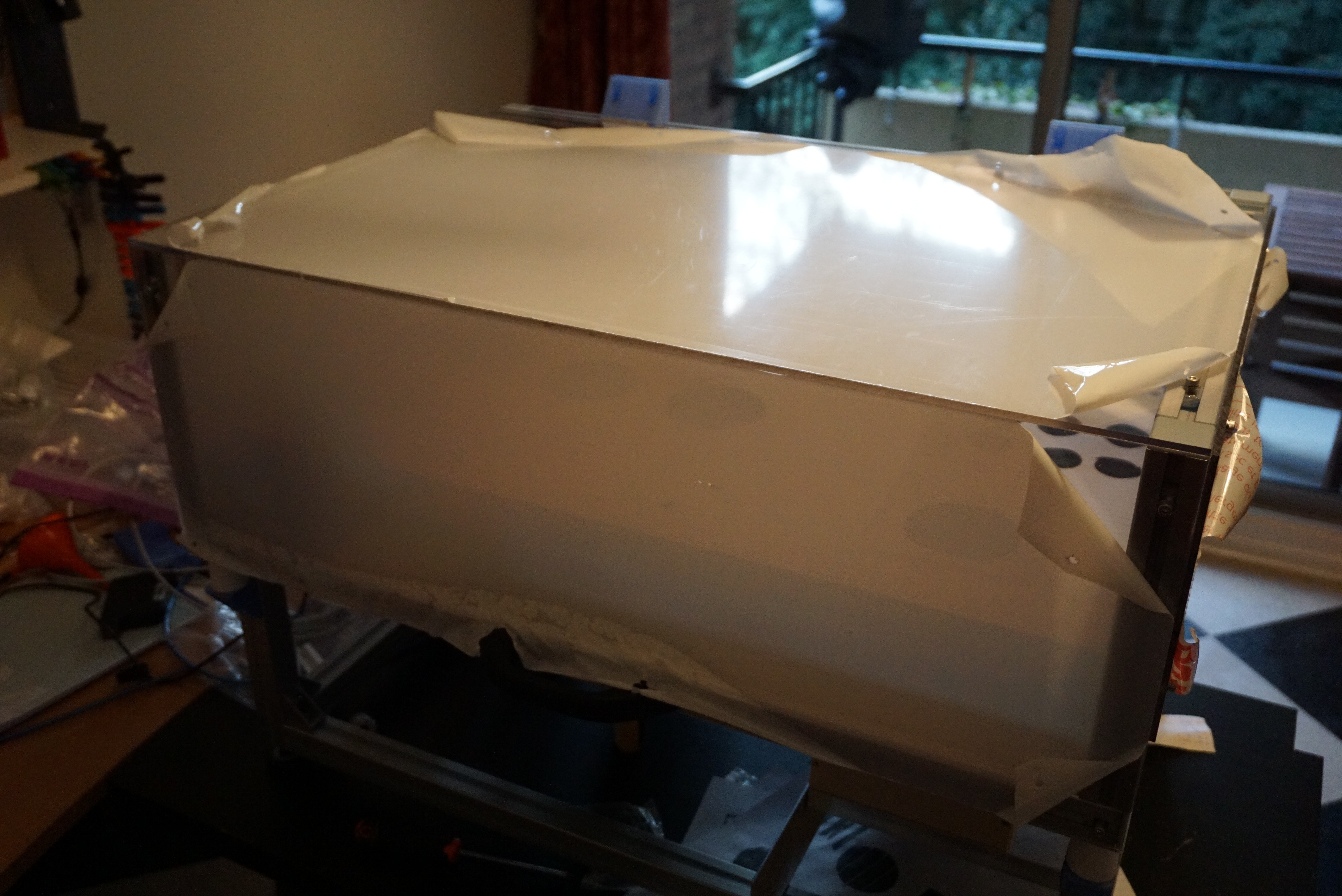
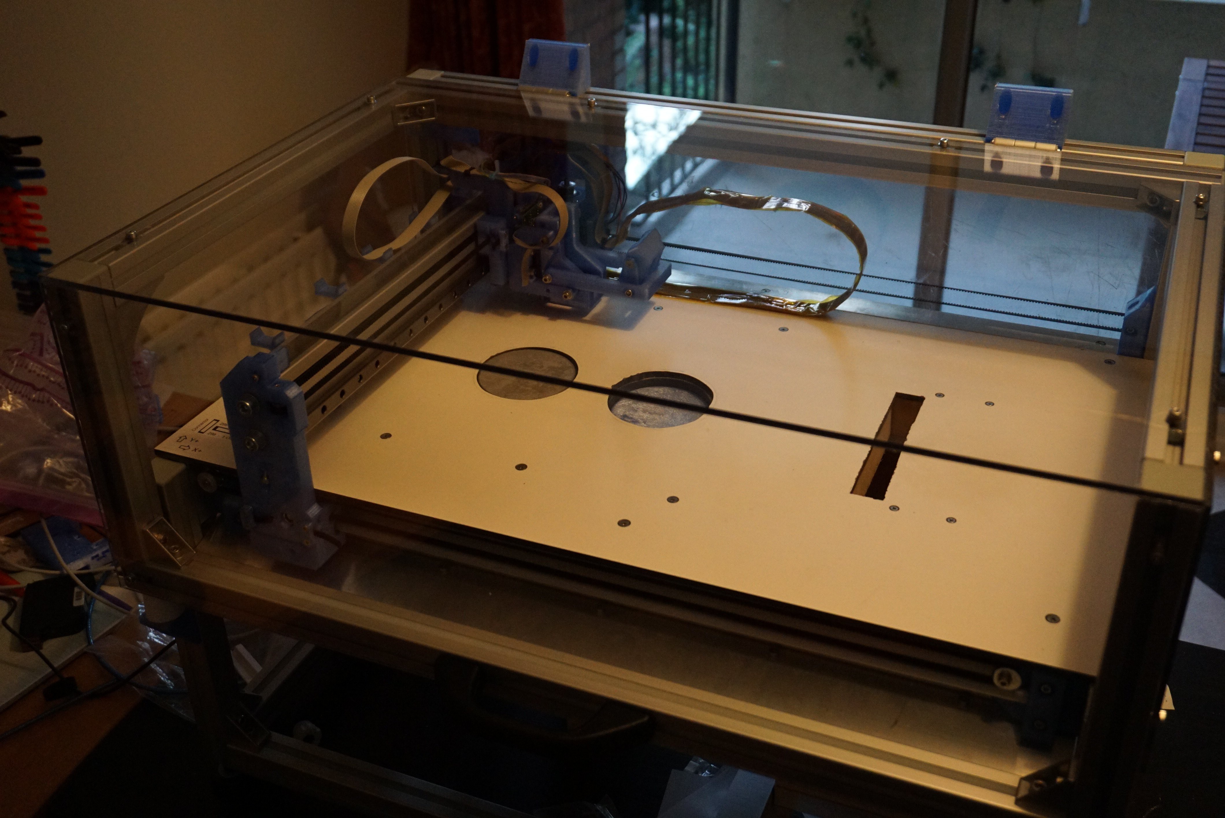
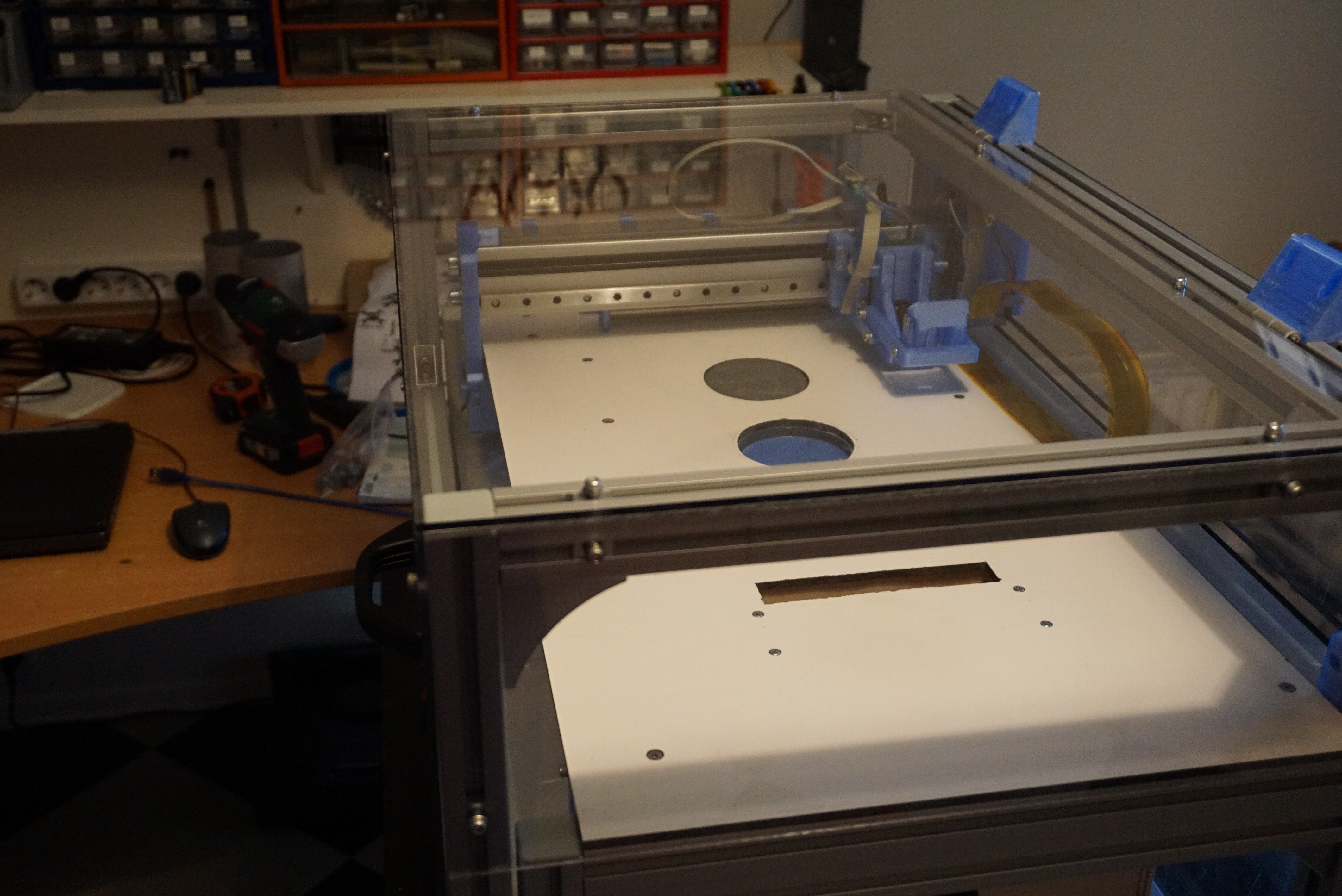
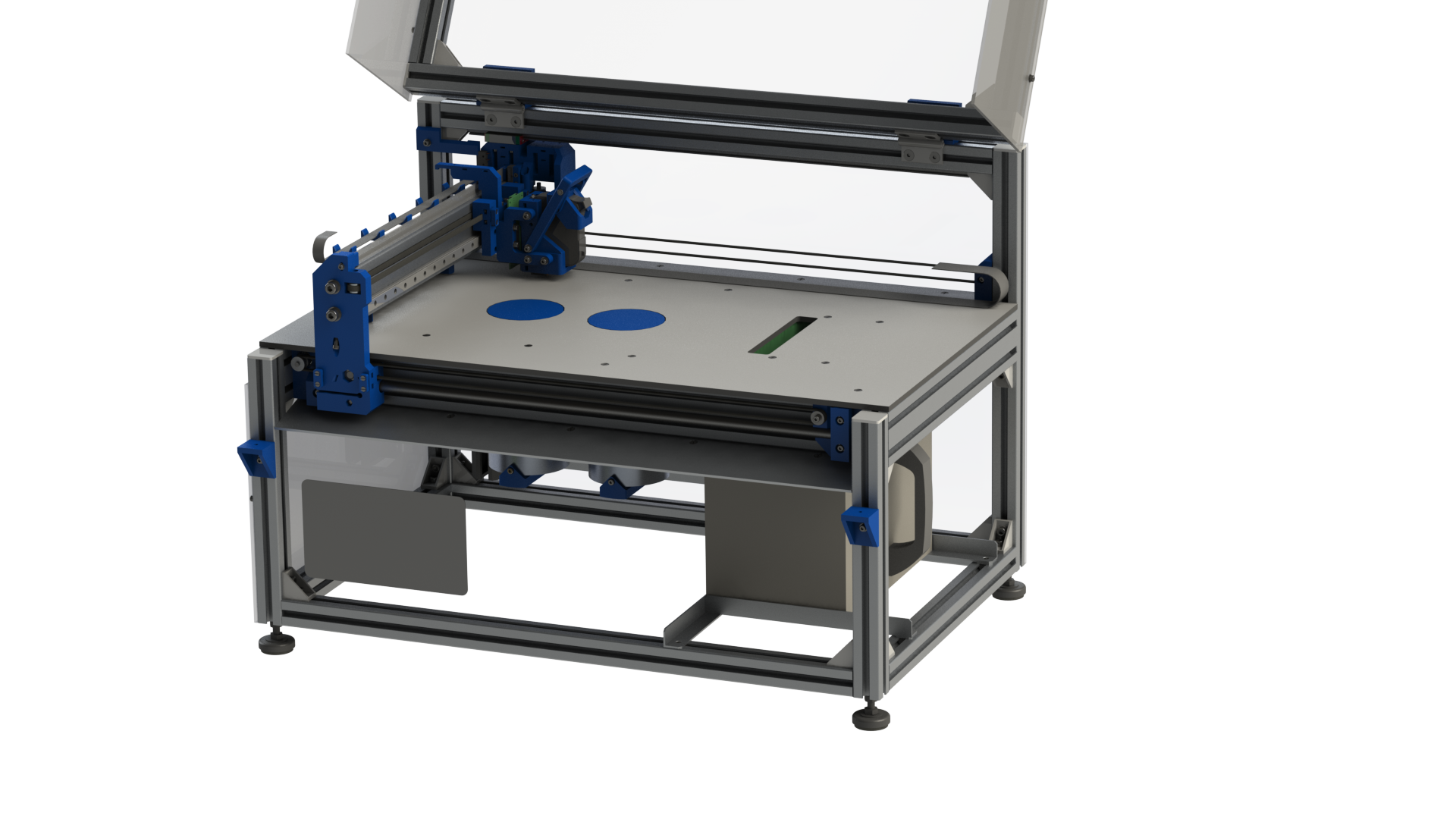
I finally added the polycarbonate to the frame of Oasis and it looks amazing. This cover serves to keep the dust from printing in, and the dust and junk from me being there out. I wanted to have it on before the powder would sit for longer times in the open.
USB cable
I finally wired the USB cable through the ribbon cable (no good photo's :( ) This was the plan all along, but now with the cover in place I needed to do it. Else I have no way of connecting a USB to the printhead with the cover closed. I will try and finish up the wiring diagram of Oasis now that I am finished.
(near) future updates
I realized that I need to give some more information on the actual HP45 connector side of things. I will do this soon'ish, as well as actually making the HP45 connector (and some of the boards) available for sale. The connectors are hard to come by in small quantities, so I had to buy a lot of them.
I will fix the printing and post processing issues I have right now, and maybe print a few more challenging parts. I will also attempt to refill a head with actual binder in the near future.
Hackaday prize video in a few weeks.
I will also start on making some of the assembly instructions, and file packages available. I do not think many people would want to start on this yet (while it is still a working prototype) but I won't let missing files be the limitation.
-
Phase 2 in progress
09/08/2018 at 18:53 • 0 commentsPhase 2 sounds really ominous. All I am doing is turning a DIY 2D inkjet printer into a DIY 3D one. Now that I am talking about it, things are going really well. An overview of the progress.
![]()
Pistons
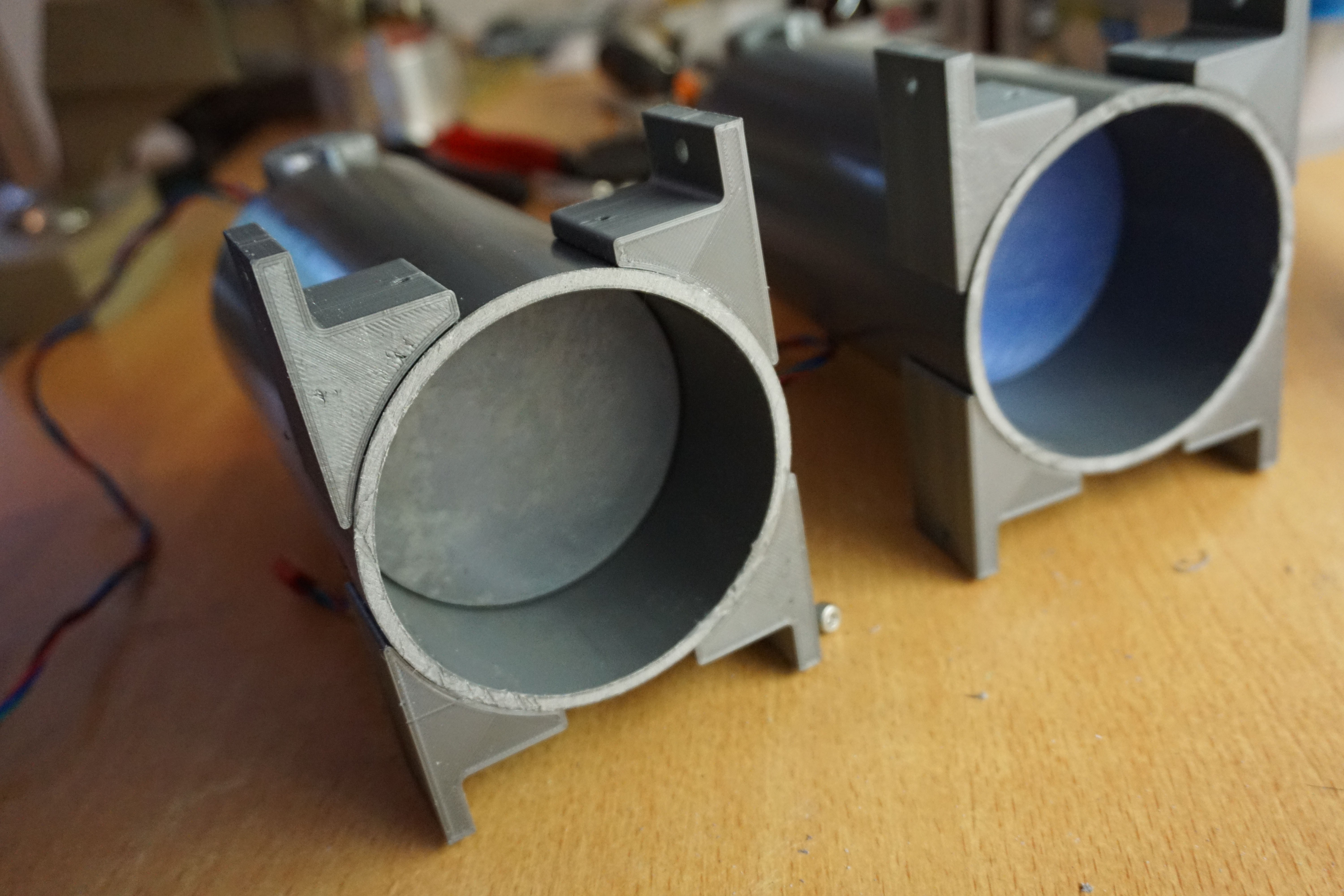
The pistons are 2 90x3.5mm PVC tubes. The design called for 90x3mm aluminium, but I had some supply issues. The effective size of the pistons is around Ø83mm by 100mm high. This will be plenty for material testing. Once I need bigger prints I will design a better hopper with more volume (or another printer with a bigger hopper).
The software for the 4th axis turned out to be a bit of a nasty surprise. The Arduino CNC shield has 4 stepper motor drivers, but that 4th driver is a lie, at least with default GRBL. I now run a special (https://github.com/mlambm/grbl) Version of GRBL that supports the 4th axis while giving up some spindle support. I can not run both pistons at the same time and this version is GRBL 0.9 (currently 1.1) (which required some tweaks in my software) but both axes move and provide feedback. I will upload wiring diagram and include the firmware with correct configuration when I can. Once I get around to writing instructions I will dedicate a section to wiring and configuring the GRBL driver. It has slowly grown to be quite complex.
Spreader
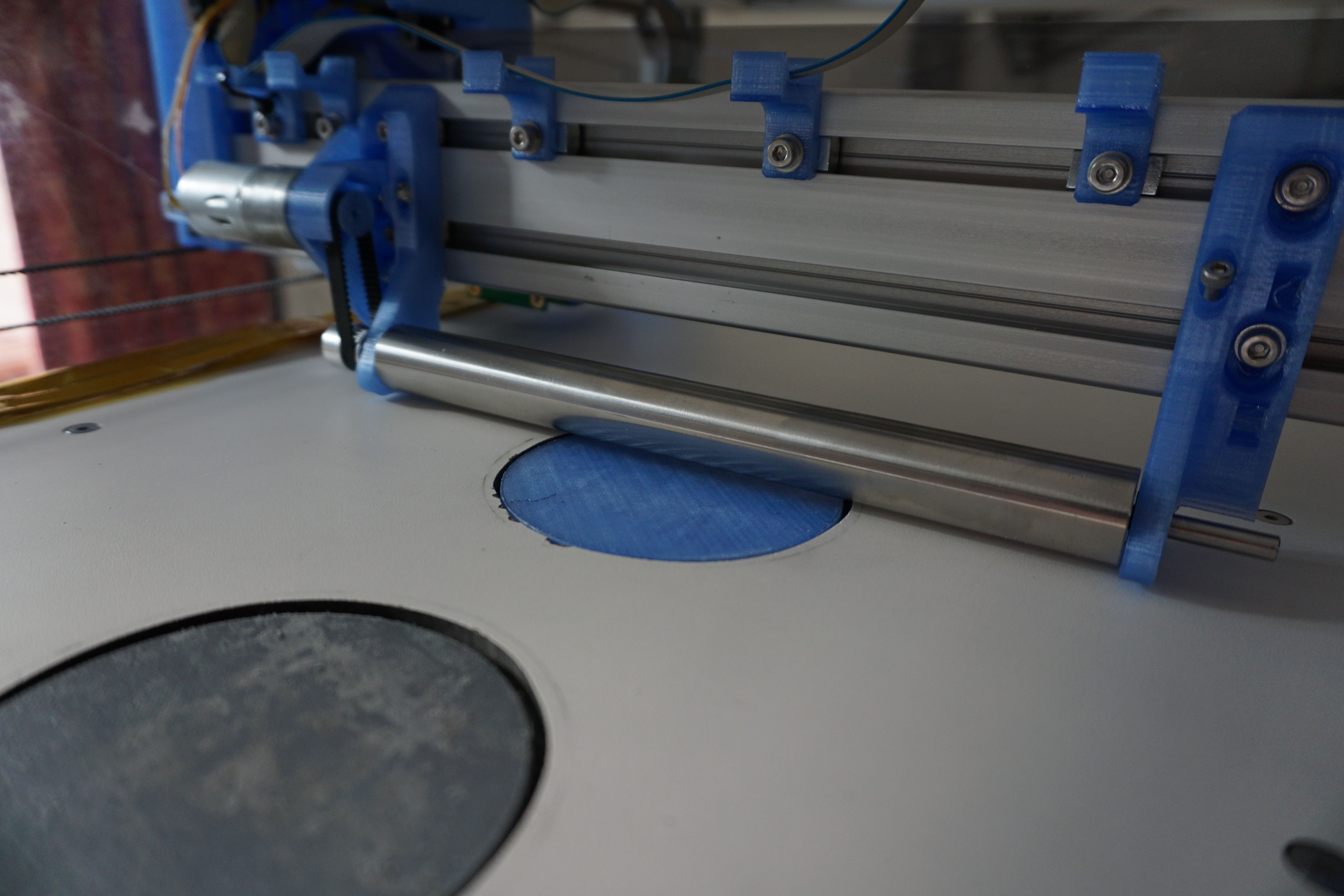
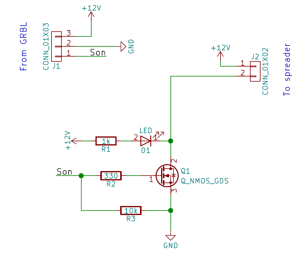
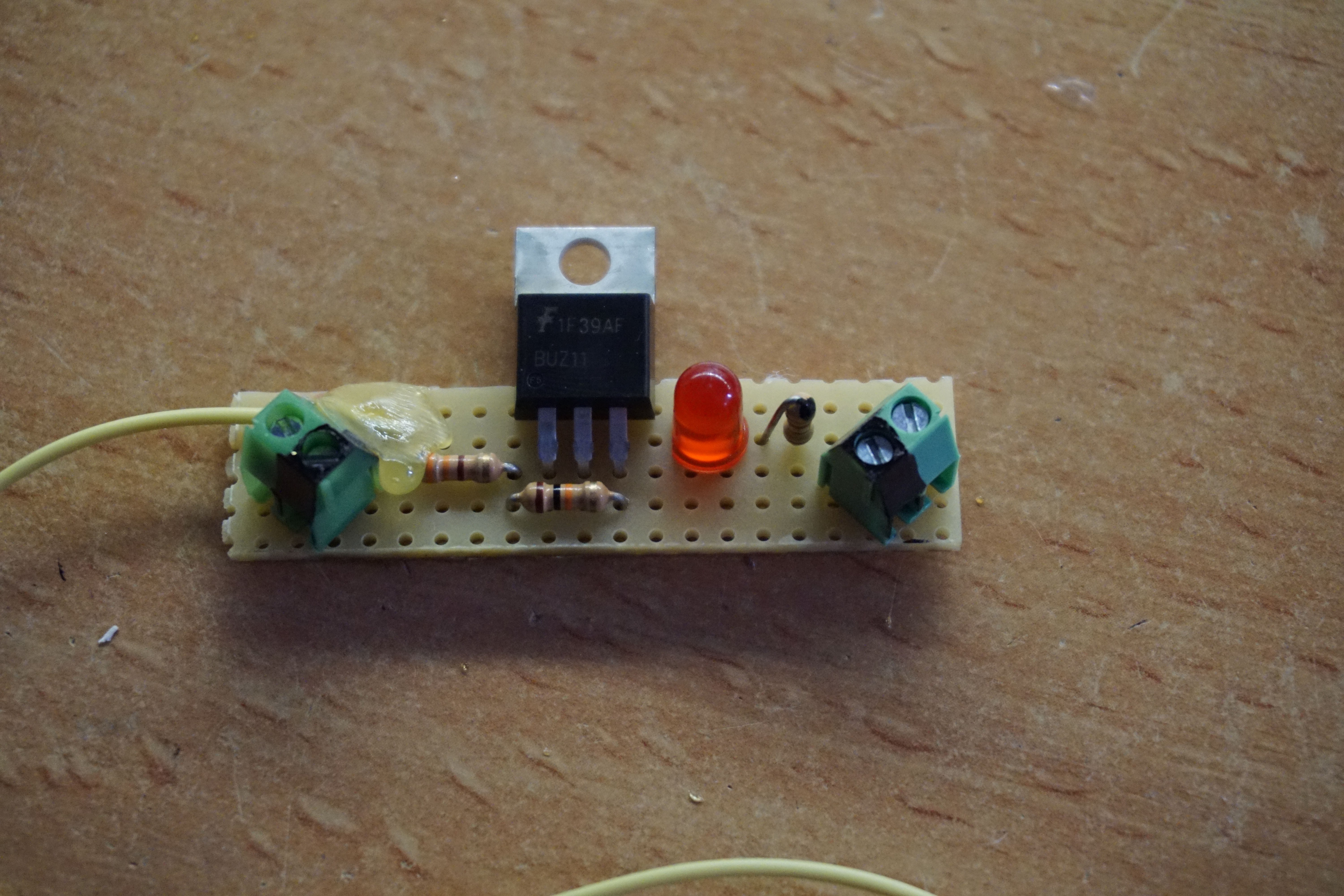
The spreader is now mounted and wired up. The CNC driver board I use does not have powered outputs, so I have made a tiny mosfet based circuit to power the spreader. I have attached the spreader to the coolant pin (which is controlled by spindle commands, yay alternative GRBL). Sending the M4 command starts the spreader, M5 shuts it down. The spreader itself uses a 12V 25mm gearbox motor at 300rpm. I have 120rpm available if 300 is too fast.
SVG file reader
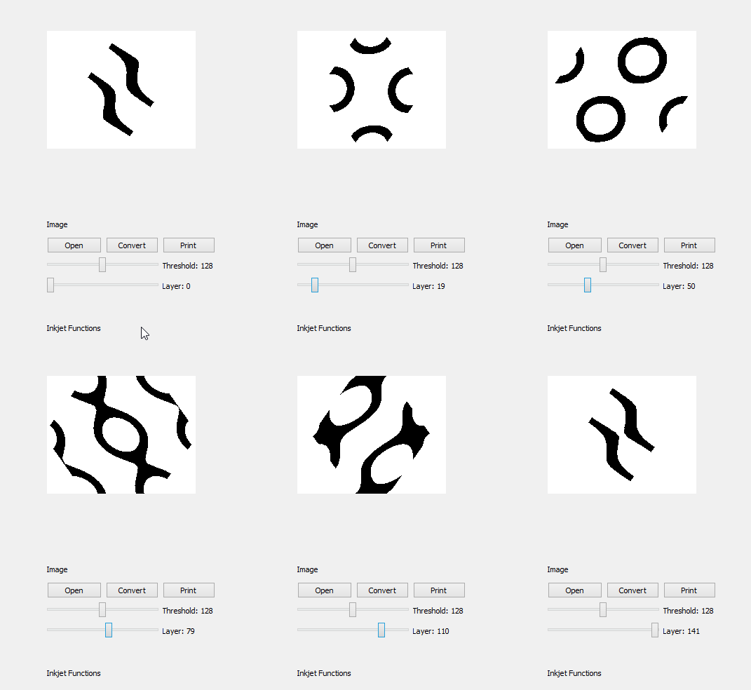
In the last log I said that I would only write a parser for SVG files myself if nothing else worked. As it turns out I lied. I wrote a parser (I had a weird day, don't judge). It only takes Slic3r SVG files, which only use straight lines and have layers. It runs just about as fast as anything else in python does (dead slow), but so far it gives clean layers. This is a great relief, because the parser was the last potential issue (lets hope).
On the software side all I need to do now is write the code that makes all the 3D printing motions and prints the right layers at the right time, but that is peanuts compared to the SVG parsing.
See below, a GIF of software reading an SVG of a gyroid.
![]()
![]()
Next log
All I need now is the adding the right code to move the pistons, and to print the right SVG slice. I also need an overshoot bin, which is easily built. When those parts are done, there should be nothing stopping me from printing in 3D. Then I can start playing with materials and binders. I have added a new package of software to the files for anyone interested.
The next log should be interesting. It won't be too soon sadly, I have a few full weekends, so expect a bit of radio silence for 2 week.
-
Commencing phase 2
08/31/2018 at 18:40 • 0 comments2D printing is now almost working. It is not perfect in several ways, but it is capable enough that I am convinced it will work for 3D printing.
What was wrong in the previous log:
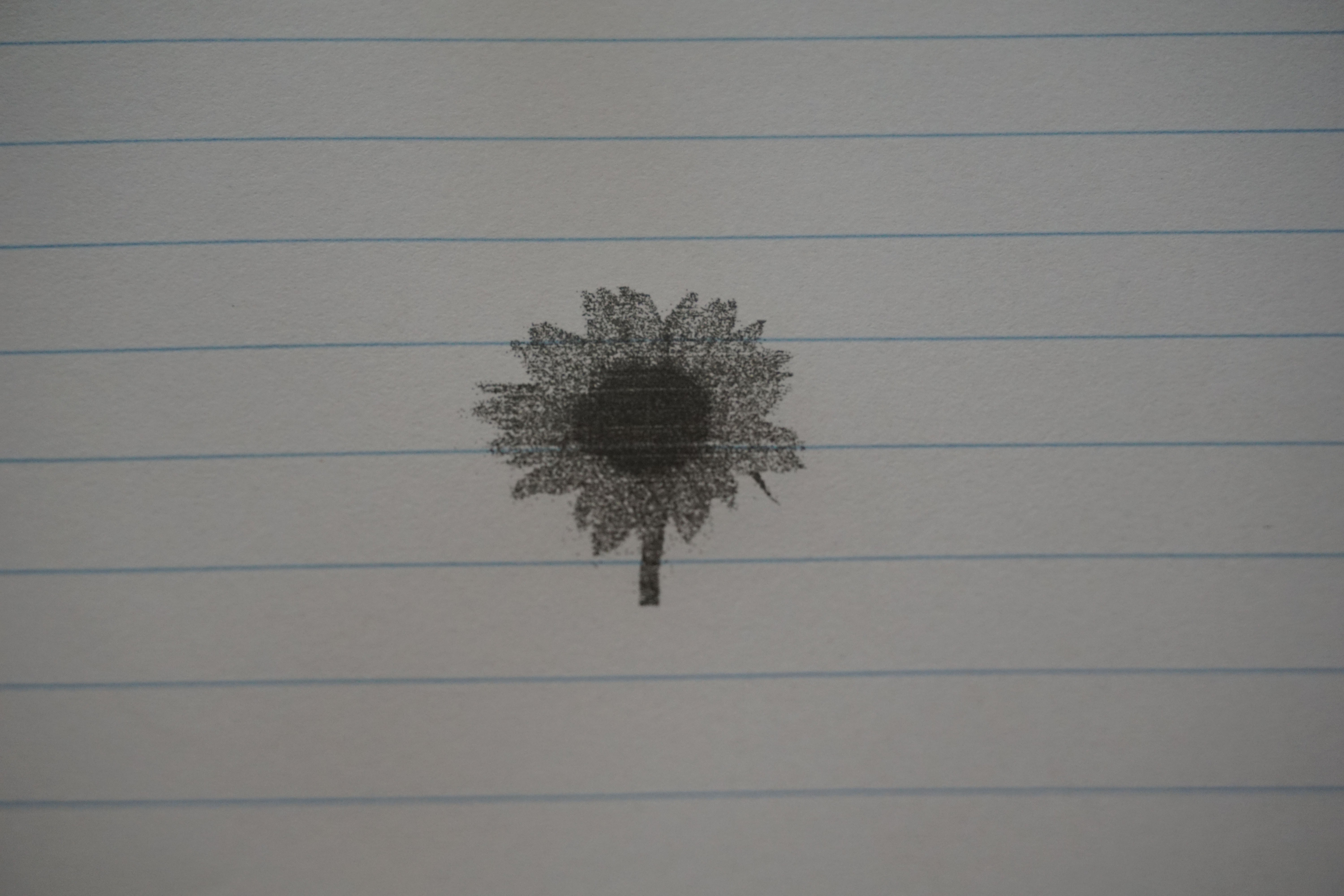
- 1 mask was flipped in the firmware. This caused the wrong row to start when the right row entered or exited the print area, cutting off 4mm of odd or even on either side of the print. The mask was flipped the right way around. The print improved immediately.
- one of the Base 64 en/decodings is the wrong way around, sending the nozzles in order 6,5,4,3,2,1 instead of 1,2,3,4,5,6. I have dug quite deep, but have not found where. I then decided that I was lazy and flipped it in the software. This turned diagonal lines from jagged to perfectly straight.
- head needed to be cleaned with alcohol before printing. The ink in the heads dries quickly, and within a minute the head becomes clogged. Simply wiping it with a paper towel helps, but cleaning it with a paper towel soaked in 70% IPA worked wonders. It gives about 30 seconds to start the print. Not ideal, but workable.
There are a few small things left to be done before I can print well enough for 3D:
- The first sweep after starting up sometimes does not print. This is firmware side and has been there since the first tests. I know where the problem happens, and have fixes ready.
- The first sweep of a print is offset by around 0,5mm. This seems to be some encoder drift from the motion between the home position and the other smaller movements. All other sweeps in a long print line up perfectly. The exact nature of the problem remains a bit of a mystery.
- At least 1 pair, probably 2 pairs of nozzles are swapped. I will do a few tests to narrow down which. If I can also identify the nozzles that are swapped with, I will fix, else I will simply disable for now.
- Software DPI setting. The software does not yet have all checks in place to change the nozzles per inch sent to the printhead. I will add this during phase 2, where it actually becomes important in the SVG parsing as well. Firmware side already handles it fine.
- mystery exit on occasion. Haven't had it for a while, but the code has mysteriously exited with a code I cannot find right now (-10#... with around 12 numbers (negative)). The problem is gone for now, but I will keep my eyes open.
There is also one issue I will not be fixing for now. I cannot properly send lines of code while the printhead is printing. Somewhere in the mess of code, probably in the Python side, the software refuses to send code fast enough. I have had other mystery issues where some threads do things instantly, while others take forever, and these same threads at other times run fast. The short of it is that I am limited to 1000 lines of inkjet code. With DPI working and set to 150, I can easily print any print I have had on Plan B with room to spare. I already had to send long dithered images before I was reaching the limit of the buffer. This is why I have decided not to pursue any fix for the 'cannot send while moving' problem until I am done with phase 2. 'First make it work, then make it better'.
Phase 2 has now started
In phase 2 I will be converting Oasis from a working 2D printer to a working 3D printer.
For this I will need to complete the following tasks:
- Designing and building 2 powder pistons. The most obvious thing I need is 2 hoppers, 1 feed and 1 build. These are going to be small, around 80-100mm in diameter. Small because every square centimeter of hopper also needs to be filled with powder, and I want to test around with powders a bit. Round because it is a shape I can buy off the shelf. Bigger hoppers will be designed eventually.
- Spreader wired up and working. The spreader is in place, it only lacked the motor when I was building it. I have to print a pulley, attach the motor to the spreader, and wire something into the GRBL driver so I can make the spreader rotate.
- Overshoot bin for excess powder. By default the feed hopper should give too much powder to ensure the build hopper is always filled. Any excess needs to be caught. Space is reserved for a bin at the end of the hoppers to leave this excess powder. I only need to build it.
- SVG to print array function (slic3r svg). Right now the software uses bitmap images. I need to add SVG to the options. I will use Slic3r SVG's for input files. Slic3r has a nice function where it exports the slices of the stl file to SVG for use in DLP printers. I have parsed these files raw on a teensy before, so using SVG tools in python should give me the option to convert these files to the print arrays that I use. If the worst happens I can write a parser myself, but that is a worst case option.
later I will:
- (priming/cleaning head station for printhead). The printhead dries out quickly, and needs to be primed before every print. The real printer has a station where it cleans and starts the head. I will eventually need something like this, though it is no priority right now.
Finally, the files for software and firmware have been updated. This version is capable (with some flaws) to send images to the printhead and print them. Soft- and firmware and 3D files will receive changes soon, this is only a snapshot.
https://ytec3d.com/oasis-download-page/
(PS. anyone with the illusion that my work on this project will enrich the world with beautiful code will have that illusion shattered the moment they see the code. I will make it work, after the Hackaday prize is done, I will see if I can get it made properly)
-
Let there be ink
08/26/2018 at 18:48 • 0 commentsFinally, after months of writing small sub systems, I can now fully print with ink.
It still has a whole heap of improvements left for now:
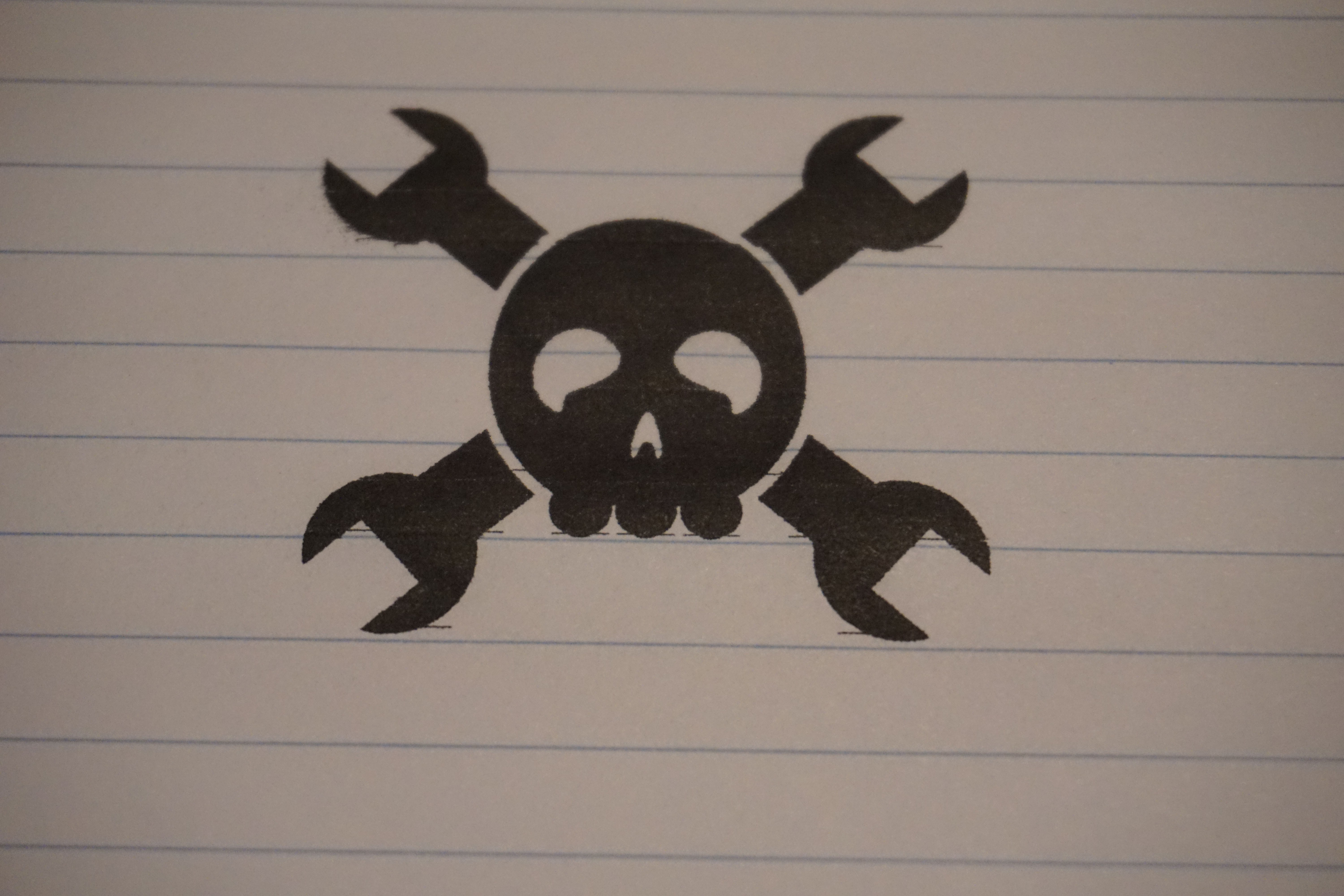
- I cannot upload code while moving (dependent on a few handshakes that are not in place yet) so I am limited to 1000 lines of inkjet per sweep. No jolly wrenchers for now :(
- There seems to be some off by one and odd even errors in both the Arduino side and the Python side. Also some ringing that I have a hard time placing where it comes from. Will play with the dials a bit once the code runs smoothly.
- The code still takes forever loading an image (though I do not care at this stage, might use something like pypy later)
- The head has a hard time properly starting, hence the missing lines (though it has been sitting drying out for over a month, it will be fine)
Next post should take less than a month this time.
(PS. Also think of the hilarious amount of effort I spent the last few months, essentially building a crappy 2D, black and white inkjet printer.)
-
Software (still) in (slow) progress
07/17/2018 at 16:45 • 0 commentsThis will not be the log that will show a working machine. I wanted to update my status because it is a month since my last log, and else people think I have stopped. I am getting there. I actually have the entire connection with GRBL working and stable, and already have a good link with the HP45. Here is a small list of what is left to do:
- Link preheat, set position, and DPI buttons;
- Make python capable of testing the printhead and display status;
- Make the python program capable of sending inkjet lines (and testing that);
- Loading an image;
- converting that image to inkjet lines;
- automatically print those lines.
After that milestone I will modify Oasis for 3D printing. That "SHOULD" not take that long since it is not adding much to the software side, but I have been wrong before.
Have an interface:
![]()
Now the news, good for me, bad for the project. Summer has arrived, and I need vacation. So the coming few weeks I will not be working on this project. No logs, probably no answers.
All the files in their most current state are now updated on my website: https://ytec3d.com/oasis-download-page/
None of it is final version, but it is last work I will do on it in several weeks.Until next time, when I hopefully can show a working machine.
-
Software in (slow) progress
06/06/2018 at 17:41 • 0 commentsI have been very busy learning Python the past few weeks. It was already on the list, and now that I really need it, I am forced to learn it with a project the size of Oasis. While progress has been steady, I have had to learn Python basically from the very basics.
The software I need to write has to do a few things.
- I need it to import images, vectors or 3D files;
- I need to convert said files to inkjet and motion codes;
- I have to connect to the GRBL motion controller and send commands to it;
- I have to connect to the HP45 controller and send commands to it;
- Use this control of both controllers to make a proper inkjet image and/or part
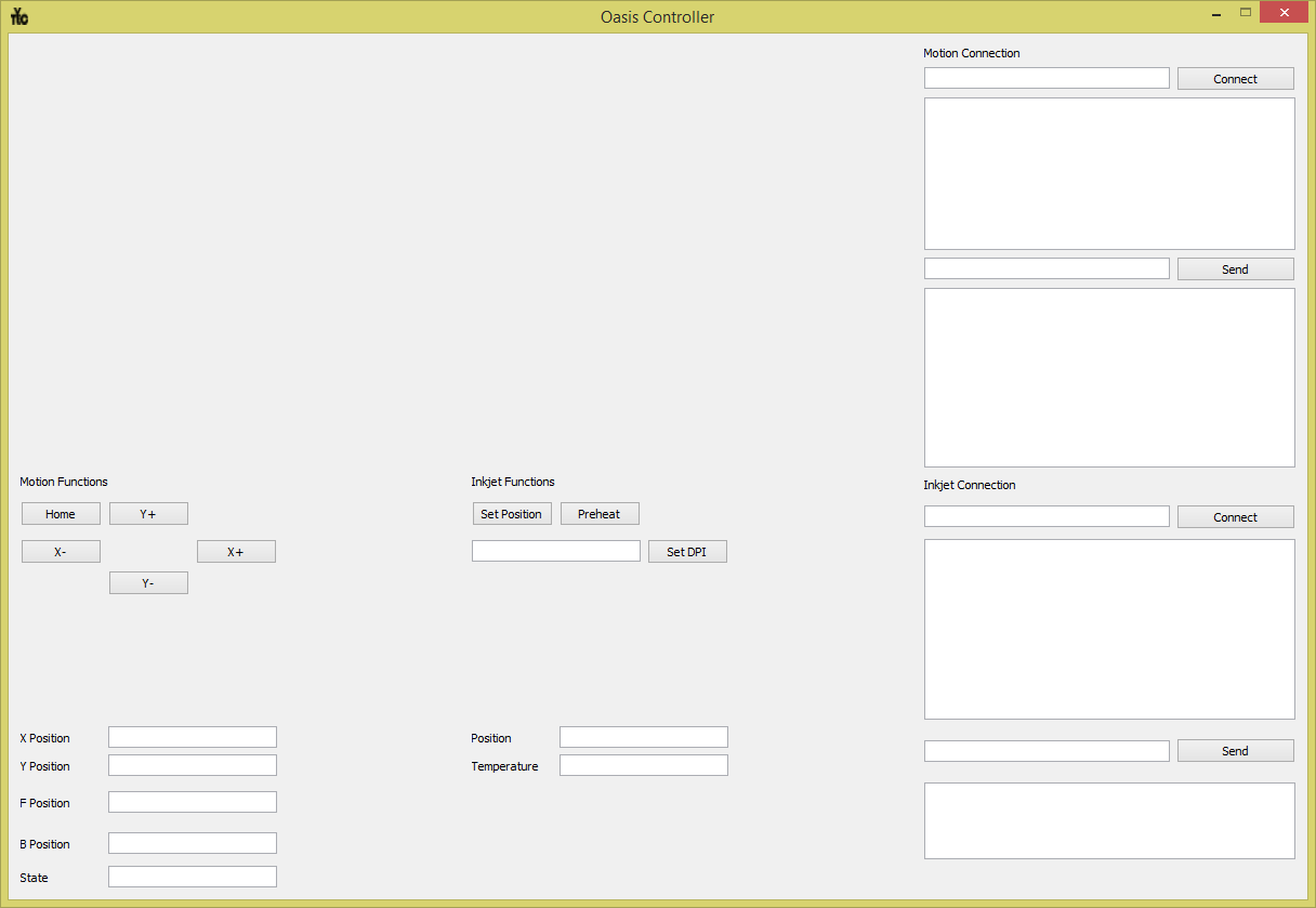
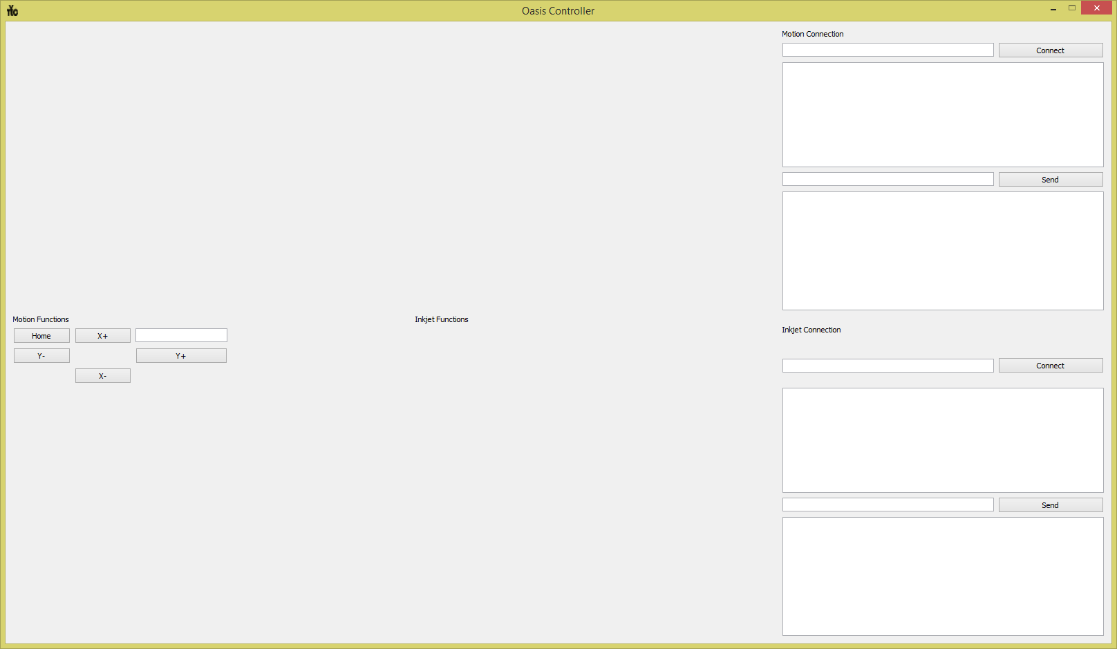
This control software will be programmed in Python and PyQT. My choice for QT is not based on any good research, I just have a little familiarity with it. A concept of the window is below:
![]()
But programming on Oasis controller directly quickly led me to conclude that I needed more experience. I left the Oasis controller for a while. I needed to learn all aspects of the program I need to write separately (and some incredibly basic Python stuff as well) so I thought of 2 smaller programs that I need to try and write before I will start on the big one.
The first is an image converter. I need to load an image, show what was loaded, convert the image so the inkjet will understand it and then render that image as well, to check for errors.
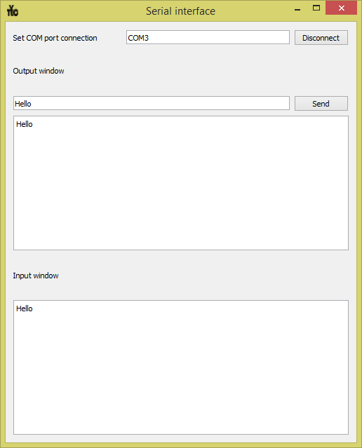
The second is a serial command terminal. Nothing fancy with automatic baudrate and connections, just, serial connect, send and receive. This proved difficult enough to take a week, simply because I knew practically nothing of python. The second one is is done. I have called it serial commander, and it works good enough that I now have confidence that I can write an interface with both the GRBL and the HP45 controller.
![]()
That is all for now. I hope that the image converter will be done a bit quicker (after the coming weekend maybe), after that I can make a proper plan on how to program the Oasis controller, and then start the final coding on that.
-
Movement and ink
05/13/2018 at 10:33 • 0 commentsThe frame is mostly assembled, and the first wiring is in. We just had a few holidays here, so I have to wait on some parts, but there is movement. This movement is coordinated by a GRBL motion controller with 2 TMC2100 motor controllers. Right now my computer is just sending raw gcode through a gcode sender tool. Later I will make the software send these commands. My first prototype of Oasis really screamed when it was moving, this is surprisingly quiet. I might swap the drivers, just for comparison later. The printhead and inkjet will be installed later, when the rest of the wiring is complete.
Speaking of the inkjet controller. I haven't even posted pictures of it yet. Last thing I mentioned was a mistake in the routing. For now I have jumper wired on my PCB to fix the issue. A new revision is ready when I find no more issues. Since then I have started programming the printhead. 2 issues, 1 bad solder joint and 1 programming mistake cost me a day of troubleshooting, but I now have the printhead working mostly the way I want to. I will spend the next week or so adding more blocks that read the encoder and read and buffer the data coming from a PC
That leaves me on software. If I were a wiser person I would have started on it already. I am not. I can't push it ahead of me for much longer though, I am rapidly approaching a point where I need the code that links the motion controller and inkjet controller together. When I finally start on that I will let it know.
First draft of CAD and firmware is now also available for download (still no github :( )
New files are available here: https://ytec3d.com/oasis-download-page/
-
Construction in progress
05/01/2018 at 20:38 • 0 commentsI made it to the finals. Yay. I was already past the point of no return on this project, but it is nice to have a hard deadline to work towards.
First there is a bit of news on the PCB's. I found a major flaw where a pin that requires digital is hooked up to a pin that only does analog read. I have upped the revision and made the changes, but I will not publish it before I have done a full test of the printhead. Who knows what else I might find. While testing I managed to destroy the microcontroller with dangling wires, which cost me a few days while I was waiting on replacements. I will continue with the PCB's shortly.
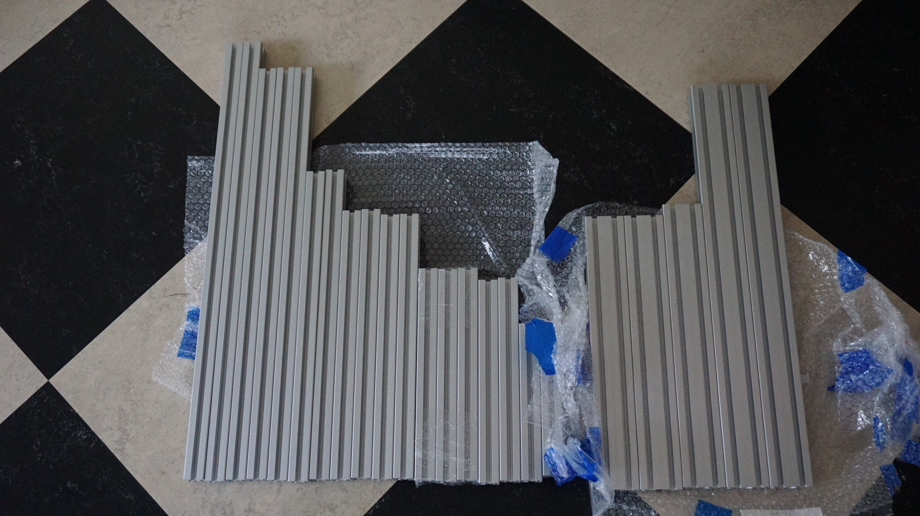
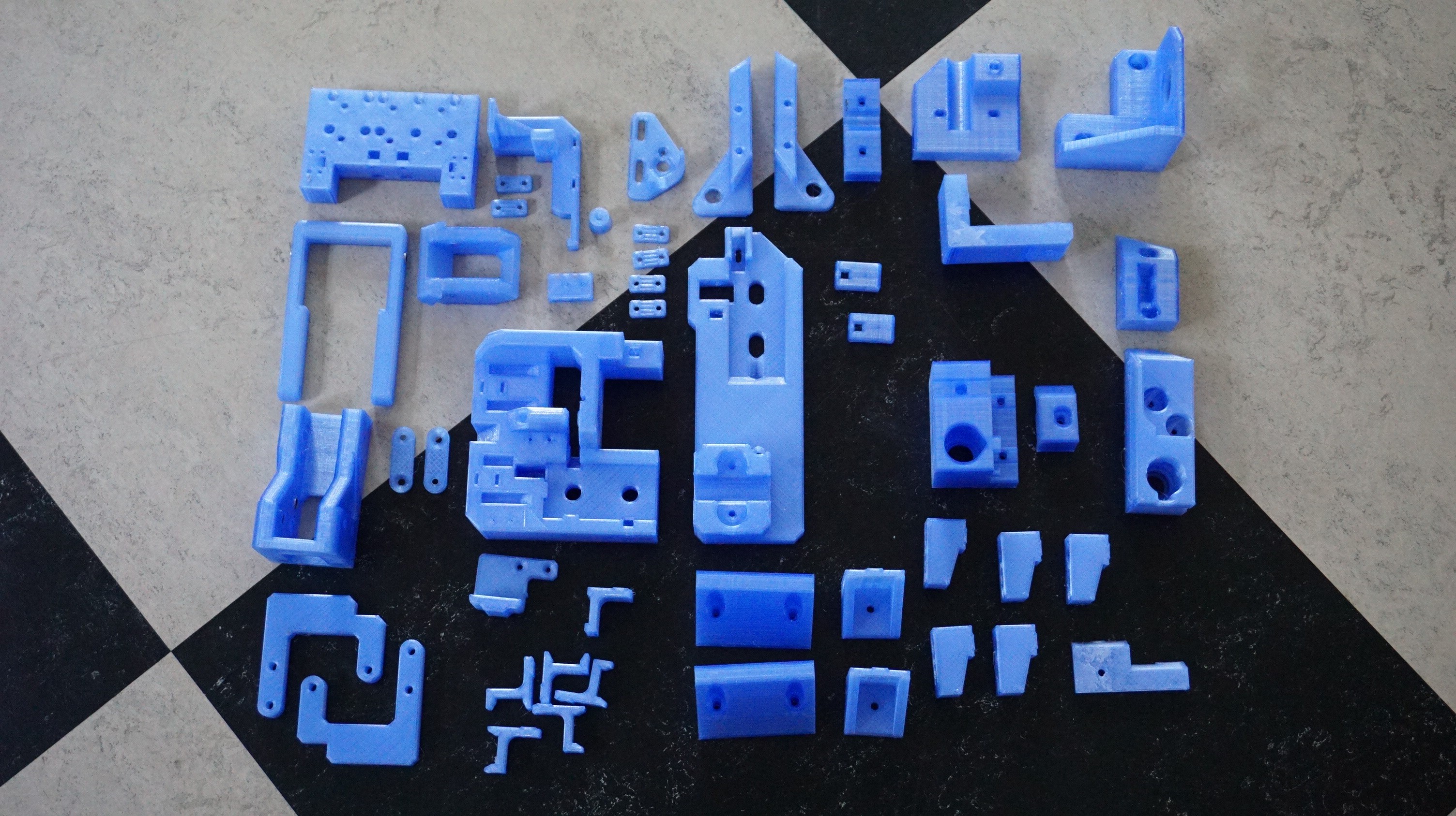
All major parts have arrived in the last week. A notable point. The Hiwin linear rails I bought from Reprapworld work fine, but they discovered that the separate carriages they sell are not compatible. I have altered the design to run on one carriage for now. It should be fine, the carriages are plenty strong on their own. Printing is also done. A few tiny issues were resolved after printing, but so far all parts came out great. No support will be needed to print the parts, which is always nice. The parts will be blue. The design was green, but I changed it to a color I liked more.
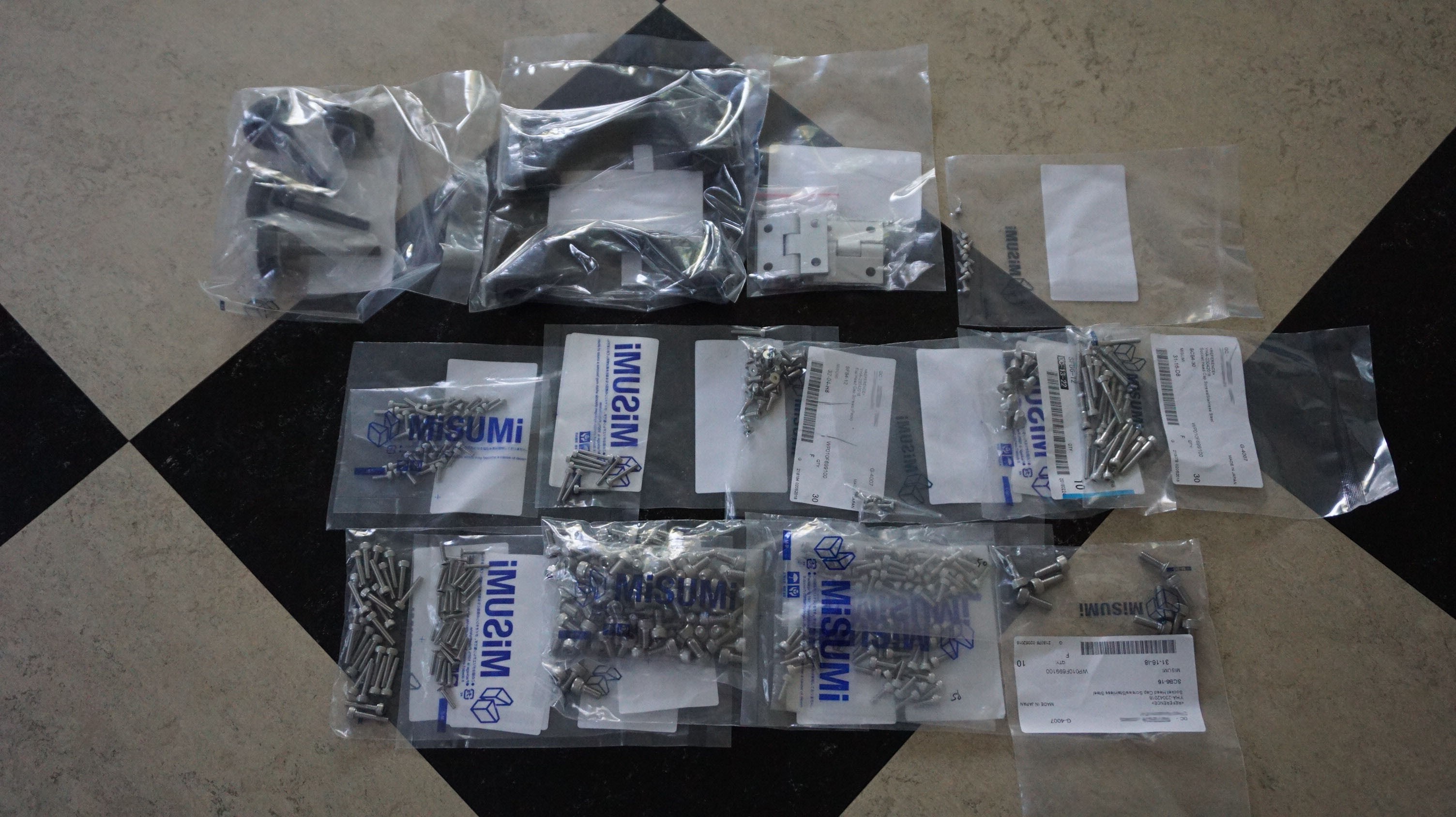
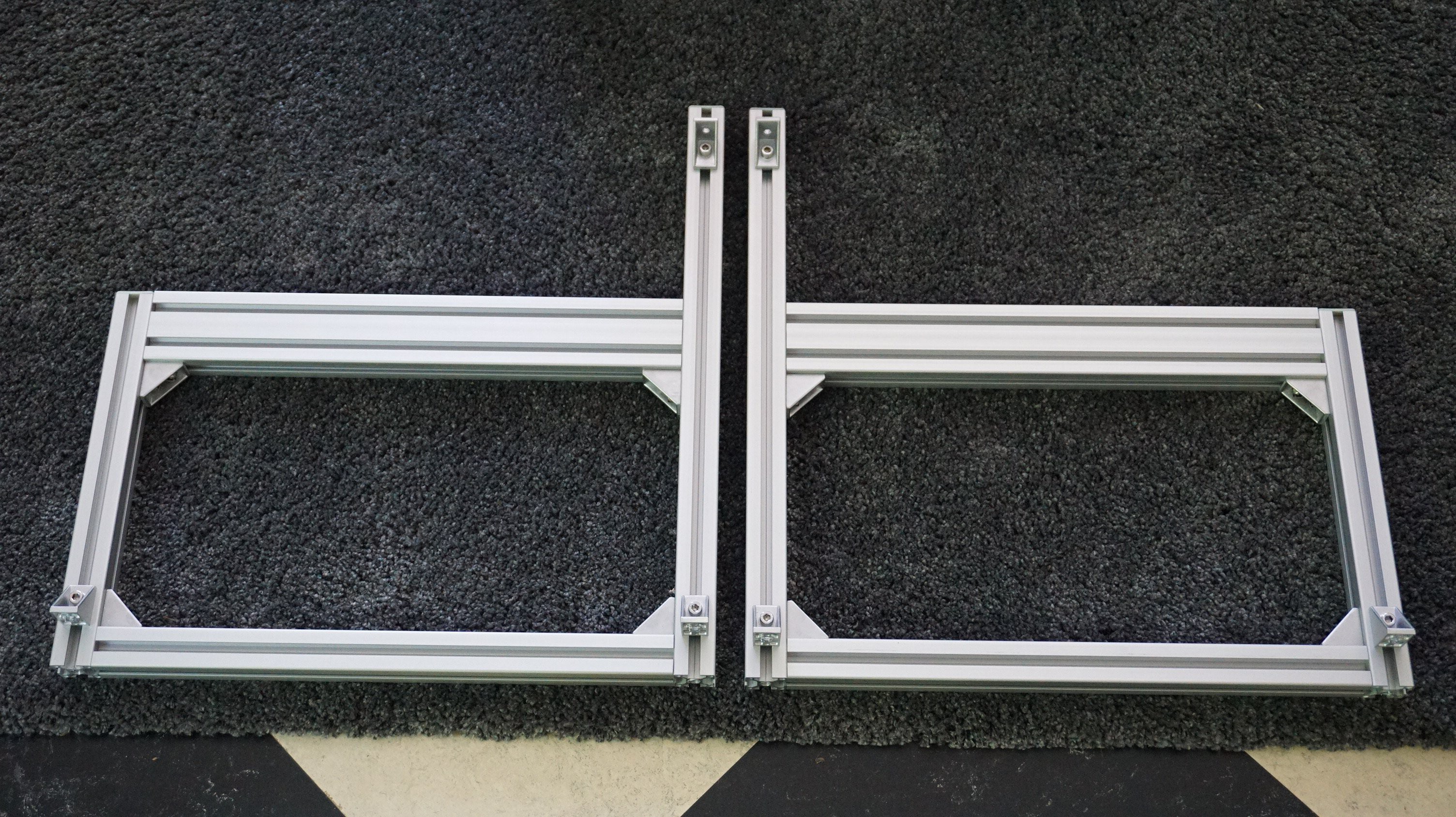
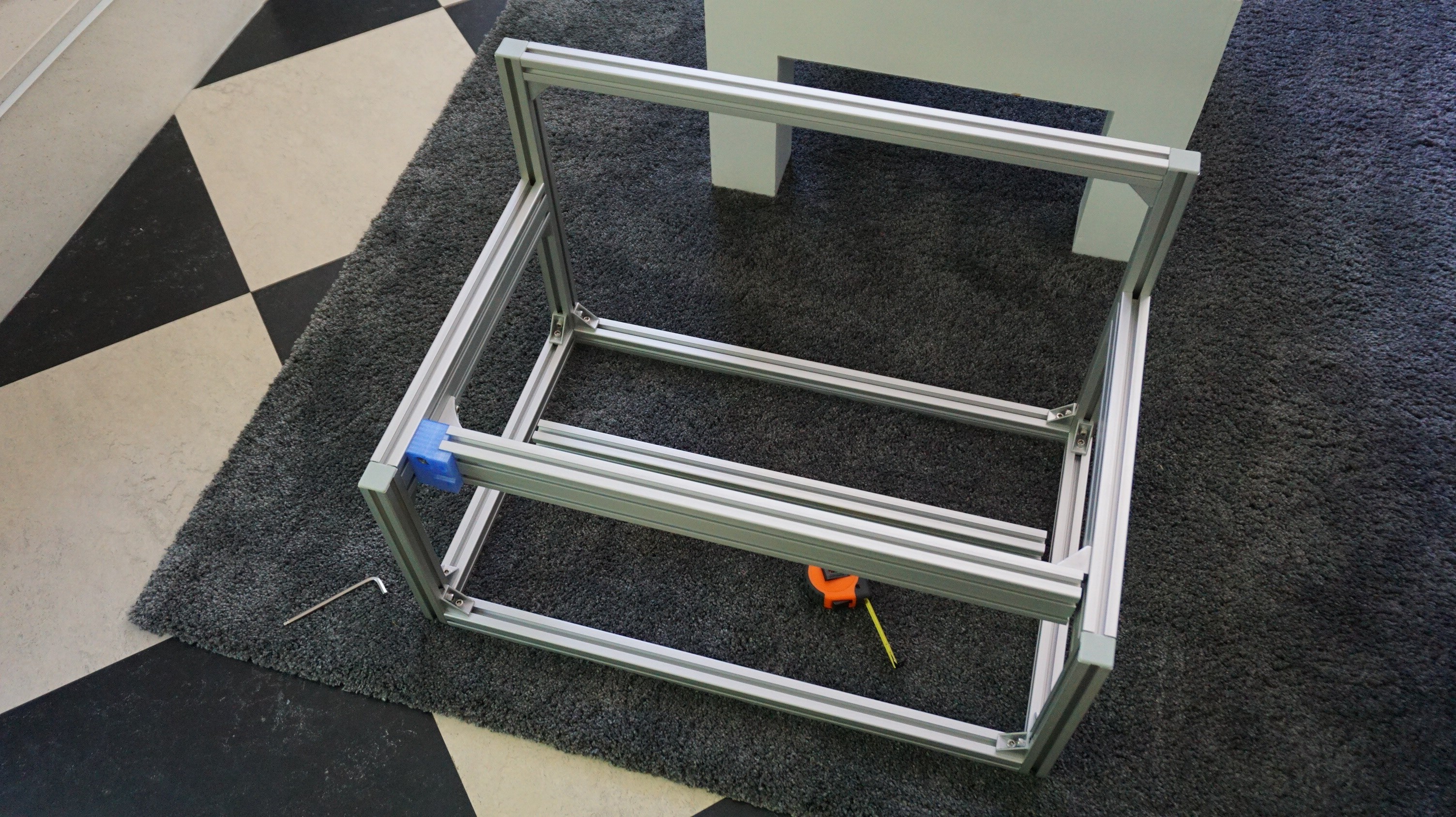
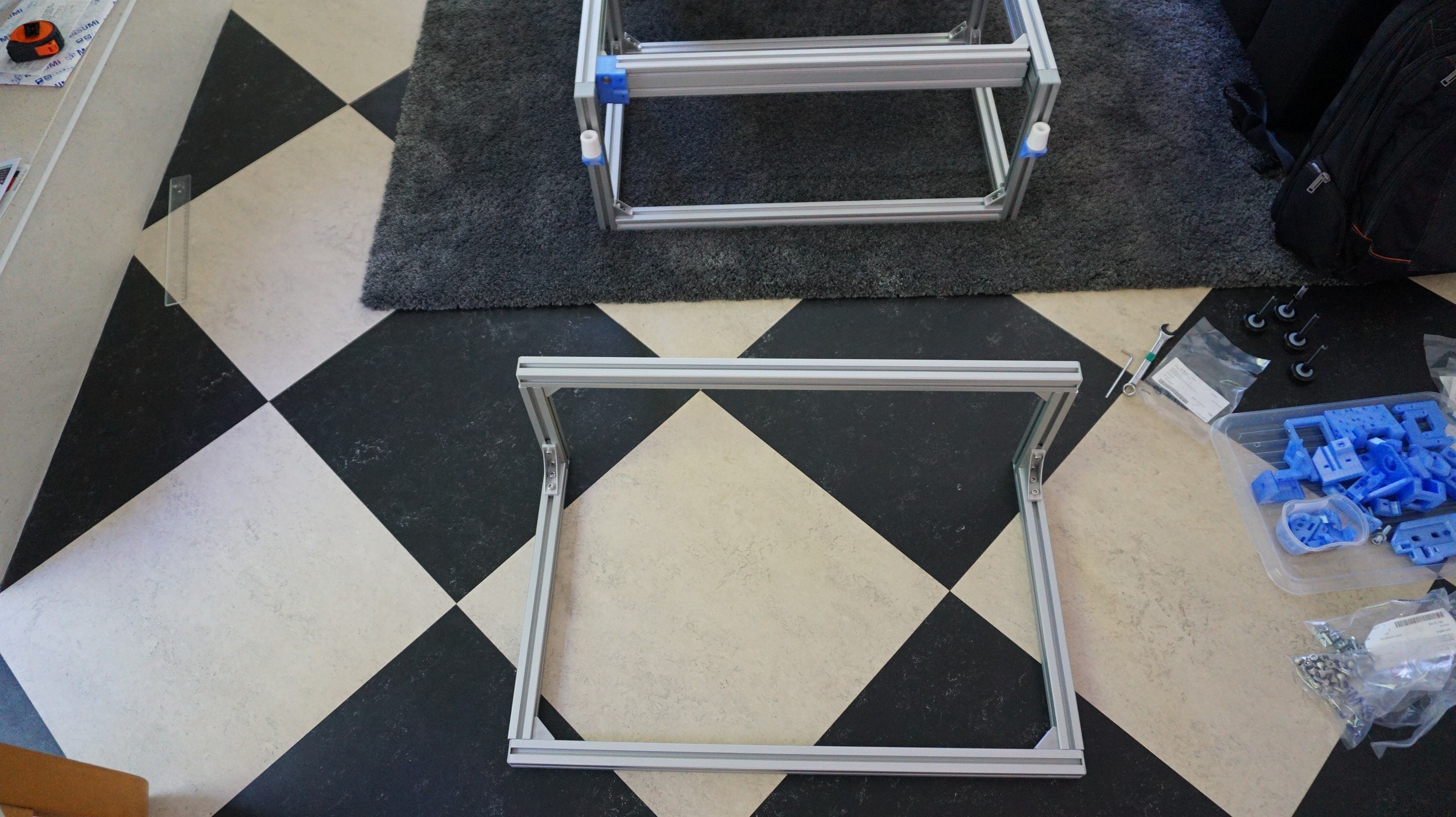
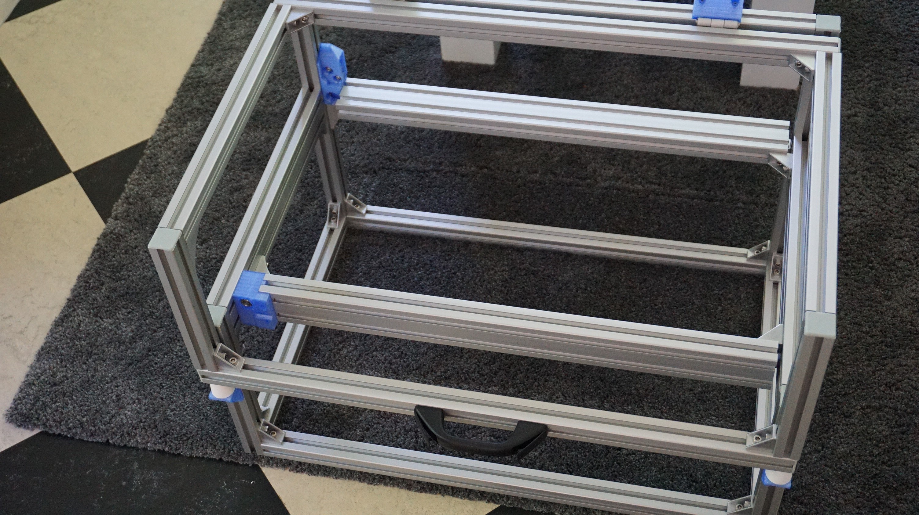
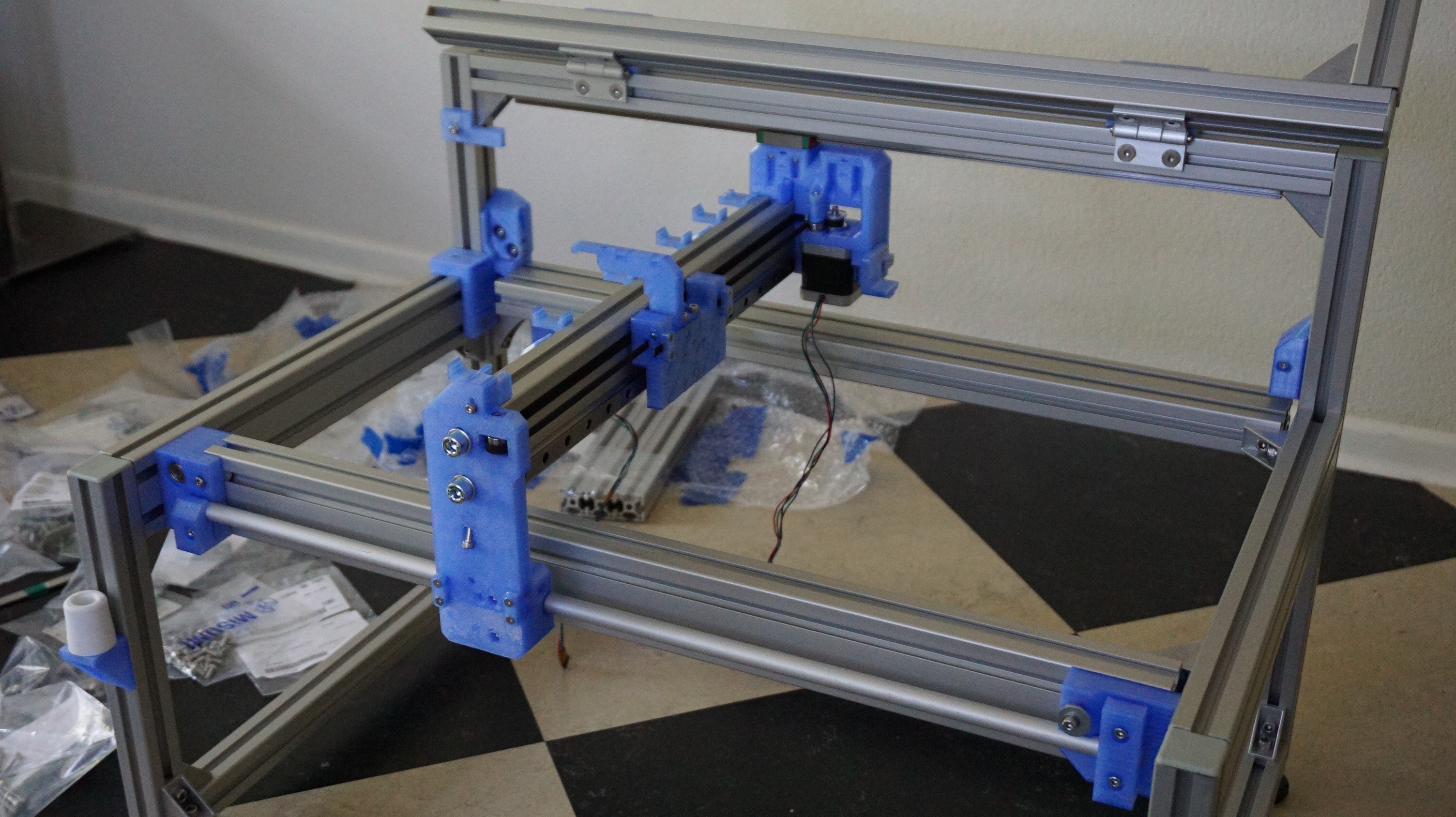
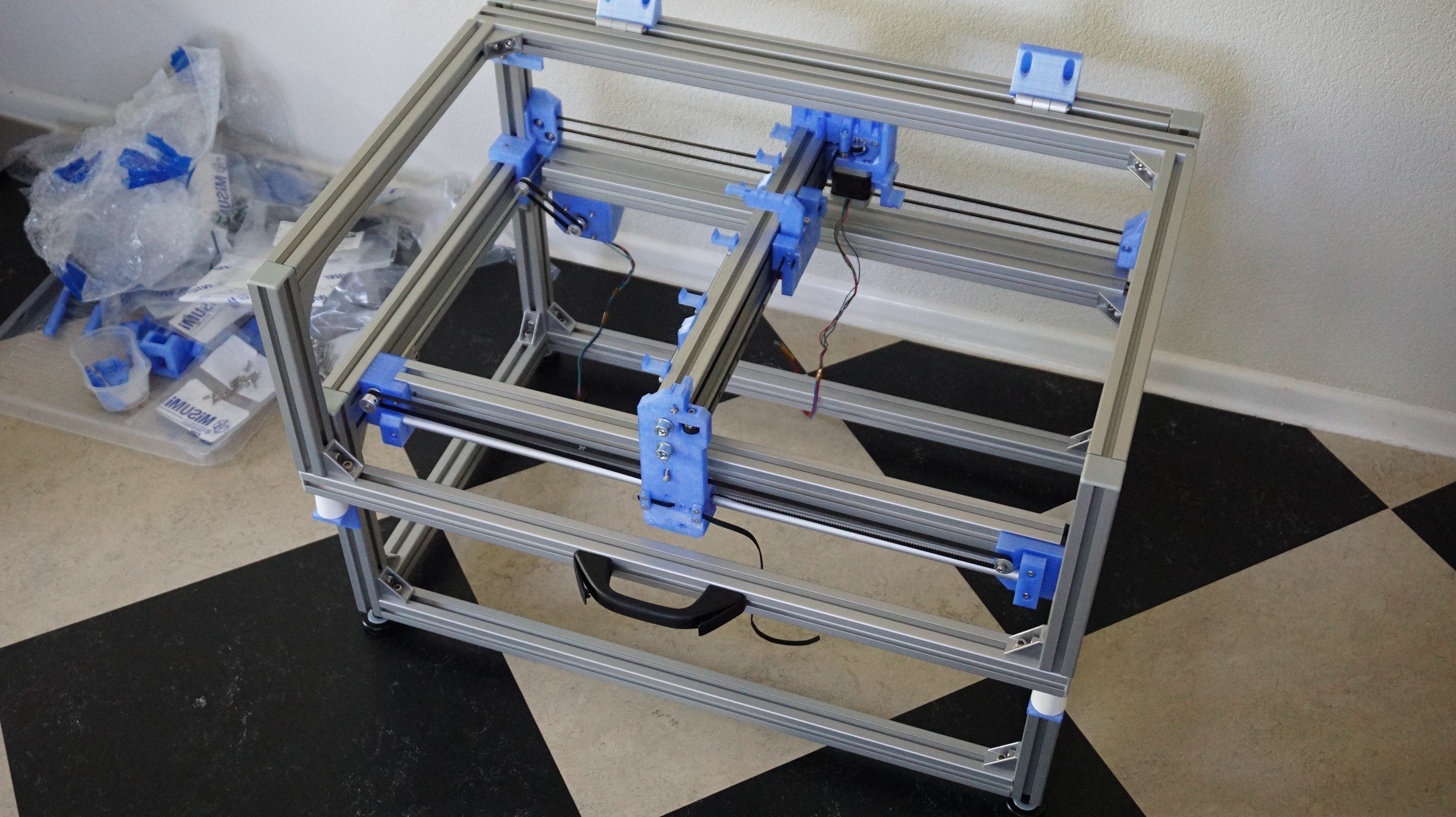
With all parts in house, I could not help but start assembling. This is a prototype, and not optimized for assembly, so I will not give full instructions right now. For now, my main focus is making this machine work. So with that said, enjoy a few photo's of me assembling Oasis.
One major mistake was found. The gantry is moved with two belts, one on the front (free) side and one on the back (fixed) side. Under the bed runs a shaft that connects the two. On the front side the belt attaches to the gantry on the bottom belt. On the back side the top belt attaches to the gantry. This means that when the motor turns, both belts pull the gantry in opposite directions. In hindsight this is a really stupid mistake, but then most mistakes are stupid in hindsight. I will fix this by redesigning the front side to attach to the top belt as well.
When this booboo is fixed, I will upload the Step files to the printer, but first I want to make sure all parts will work. In the next major log I hope to have movement.
-
PCB's have arrived
04/20/2018 at 17:36 • 0 commentsA short log, while I am making a start on the mechanics. The PCB's have arrived. I would have populated the boards and done some tests, but in en extreme case of murphy's law, I have lost the one bag of components I need the most. The missing components are scheduled to be found after I have ordered a new batch of said components somewhere this weekend.
I am also ready to order the big frame pieces, start on 3D printing and some other tiny things I need to do before I can start the assembly. Expect some progress on the frame in the next few weeks as well.
