 Maciej Witkowiak
The software part is ready. It may need some tweaking and I still don't know what LCD should display in 3rd mode or what should go to OLED screen (even if there should be OLED screen), but the control and display parts on the Arduino Micro/Mini side are ready.
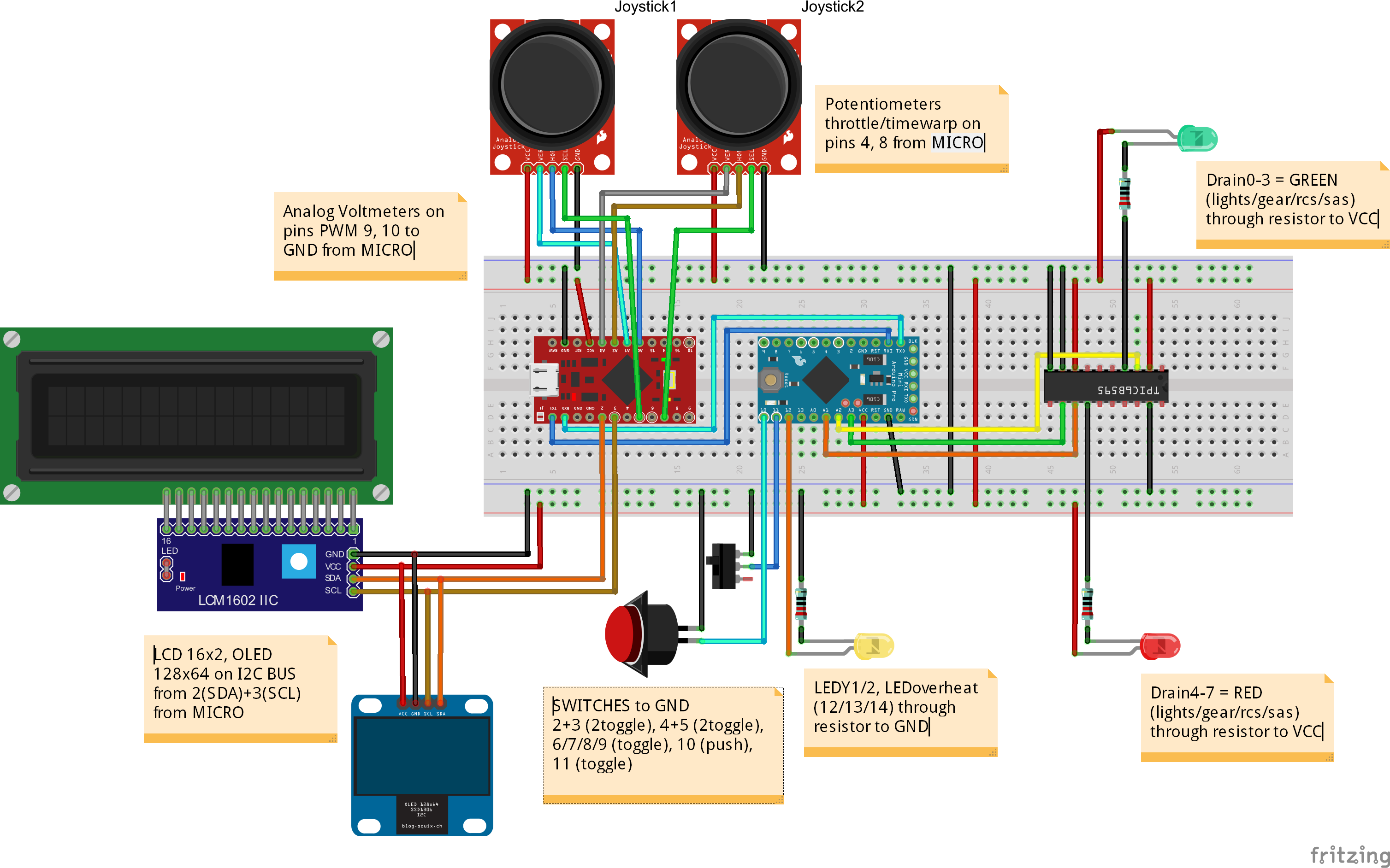
What works:
- digital input (switches) - either to change mode of operation (LCD display mode, joystick axis/rotation switch) or operate as a button
- analog input (potentiometers) - two X/Y joysticks and a potentiometer mapped to X/Y/Z/throttle/rudder joystick axes and one additional potentiometer for timewarp control
- analog output (voltage display) - works nicely, but there is power issue (see below) to be solved
- translation of switch+potentiometer actions to a emulated joystick with 8 buttons and 6 axes (X/Y/Z axis+rotation), throttle and rudder
- LED display - off, on, blink
- LCD display - connected through i2c to save time and space
- OLED display - will work, I have no use for it right now but there should be enough flash left for u8glib library and some display code; in the worst case it will have very low refresh rate and most of the processing will be done on the PC host side
There is a problem with providing enough power to the circuit. I don't know which part is at fault right now. Either Arduino Micro Pro doesn't negotiate enough current, or its voltage regulator limits available power. With only two uC running the analog voltage display shows me 4,1V on the scale. Earlier tests showed me that with blinking LEDs both analog display and potentiometer readings will swing.
This is the schematic with main components done with Fritzing:
Discussions
Become a Hackaday.io Member
Create an account to leave a comment. Already have an account? Log In.