- Powered by Power over Ethernet (uses similar design to my previous hackaday project PoE IoT sensor), with Ethernet sent onto the RPi via a second RJ45.
- Schematic and PCB done in Kicad, PCB made by www.elecrow.com ($9.50 for 10 boards, excellent quality - I recommend this board house). Also the new release of Kicad with the push/shove router is so nice to work with.
- Using optocouplers for inputs to isolate any external interference / voltage spikes from the Raspberry Pi / network.
- Windows 10 IoT used as the development environment is better than the Linux equivalent (more integrated - develop and test on a PC and click deploy to remote machine to run on RPi).
- Daughterboard uses a small 1W amplifier for audio output (connected to RPi audio out)
- LED and LDR connected to RPI GPIO via a transistor. LDR varies the GPIO voltage between 1v and 3v depending on light conditions with a 1uF capacitor used for hysteresis (avoid over-triggering in low light conditions).
- Using a modified version of the Windows Universal real time video chat sample for video / audio between the Pi and a PC.
- Uses MQTT for messaging back to the home automation system. The HA system looks after the gate opening, video viewing, WhatsApp alerts, logging etc. and is out of the scope of this project posting (post a message to the project if you want to know more).
Currently the board is made (with a number of silly mistakes later patched - rushed the design / routing of the board and didn't double check....) but the version published on GitHub has these fixed. Working so far is the PoE, all inputs, LED and LDR, webcam and the software is working but unpolished (at this point).

 Louis Parkerson
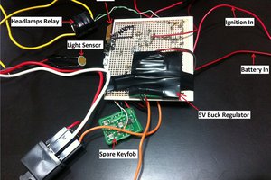

 danielmcgraw
 PixJuan
Your endeavor is incredible. This endeavor has given me a lot to learn. I'd want to distribute it to the team visit here so they can read it and apply something fresh to our ongoing efforts.