The first day of this project was pretty fun, and I made some decent progress. I wanted a way of moving two sets of 8 electrodes down in small steps, rotating one set. With some scarp tubing, a plastic cricket stump, some screws out of an old printer (and a spring from the same), a coffee tin lid, a bottle top, a few stepper motors and some rails (also from the printer) I got it working fairly well. Here are the steps I followed:
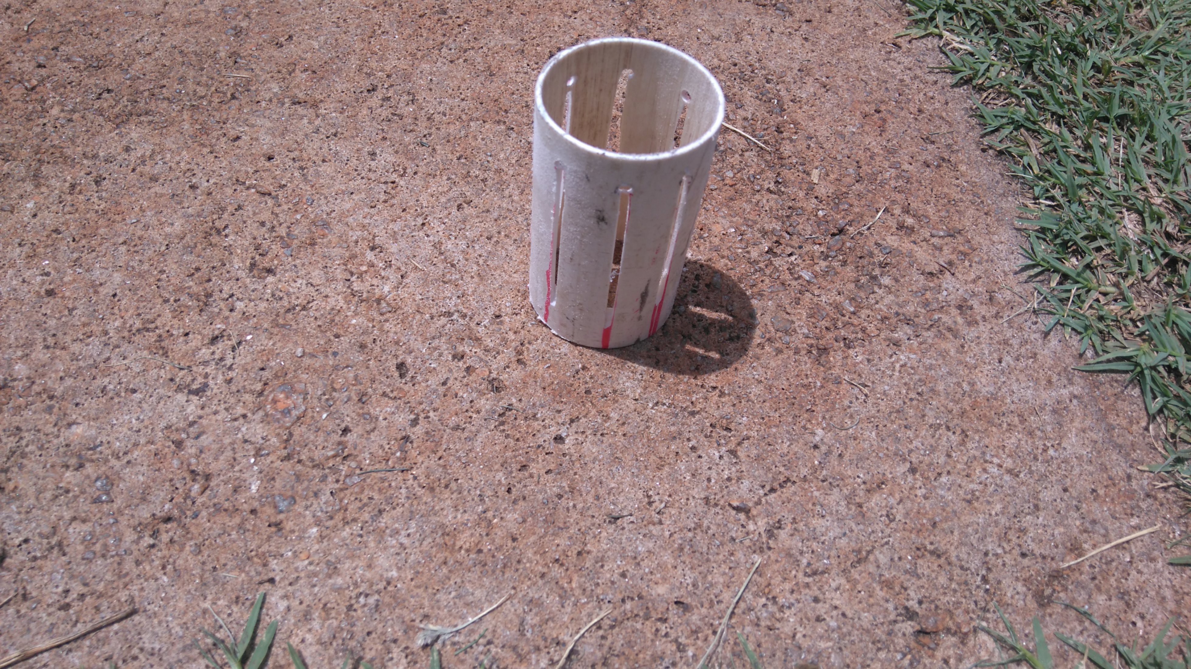
The cricket stump (red, not shown) fits inside some PVC I had, so I drilled 8 holes through both then cut channels in the PVC, using the rest of the stump as a guide to make them strait(ish).
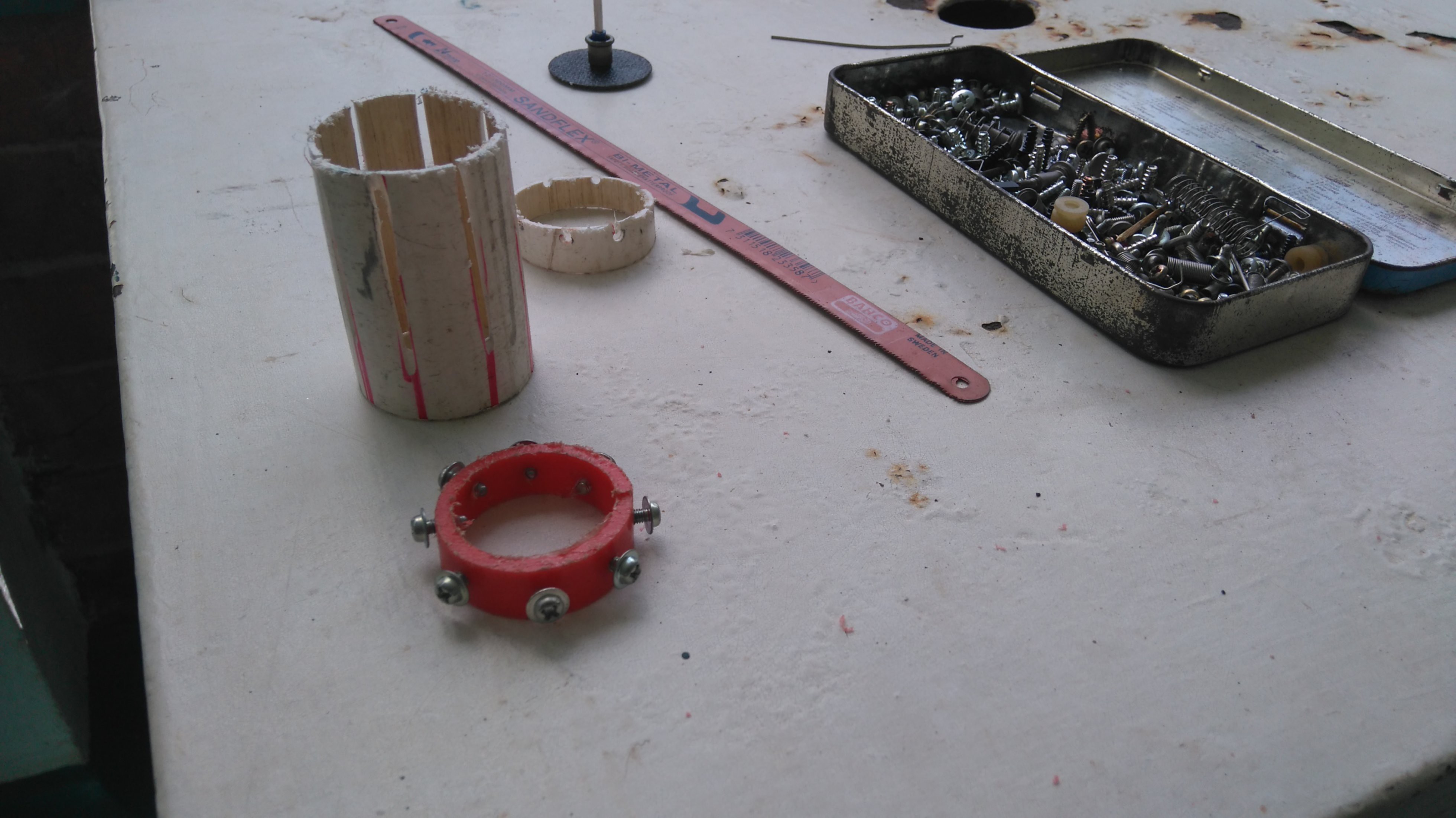
I added screws to a slice of the stump, and filed the channels in the PVC until they all matched up:
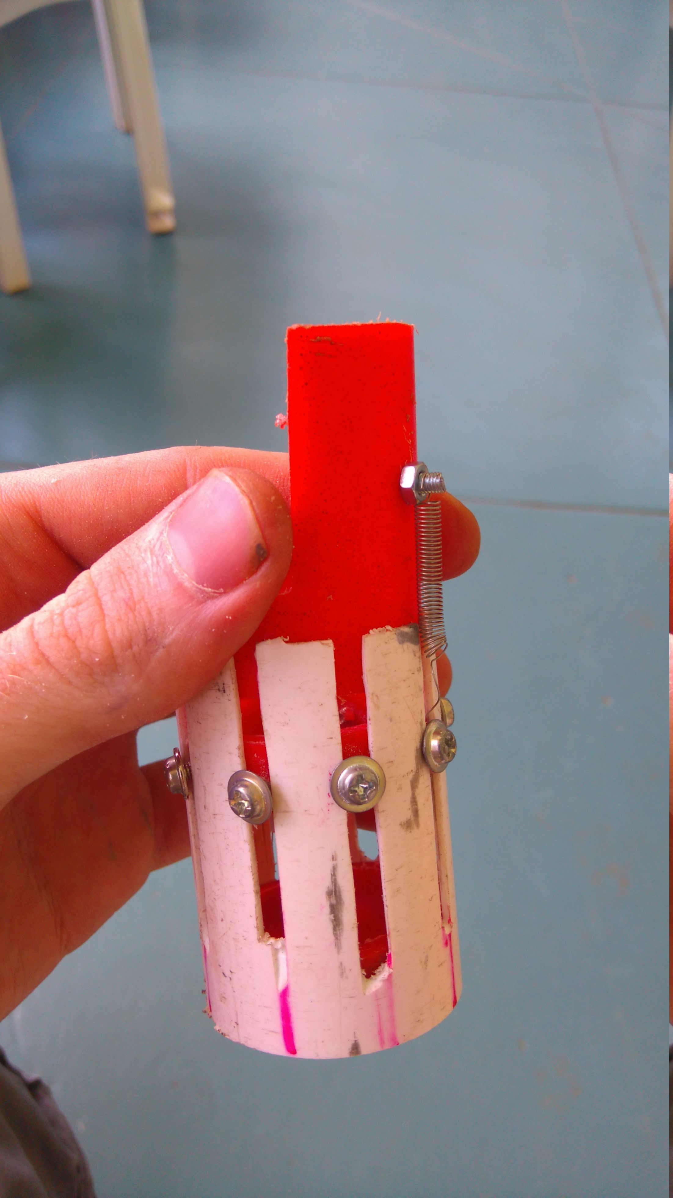
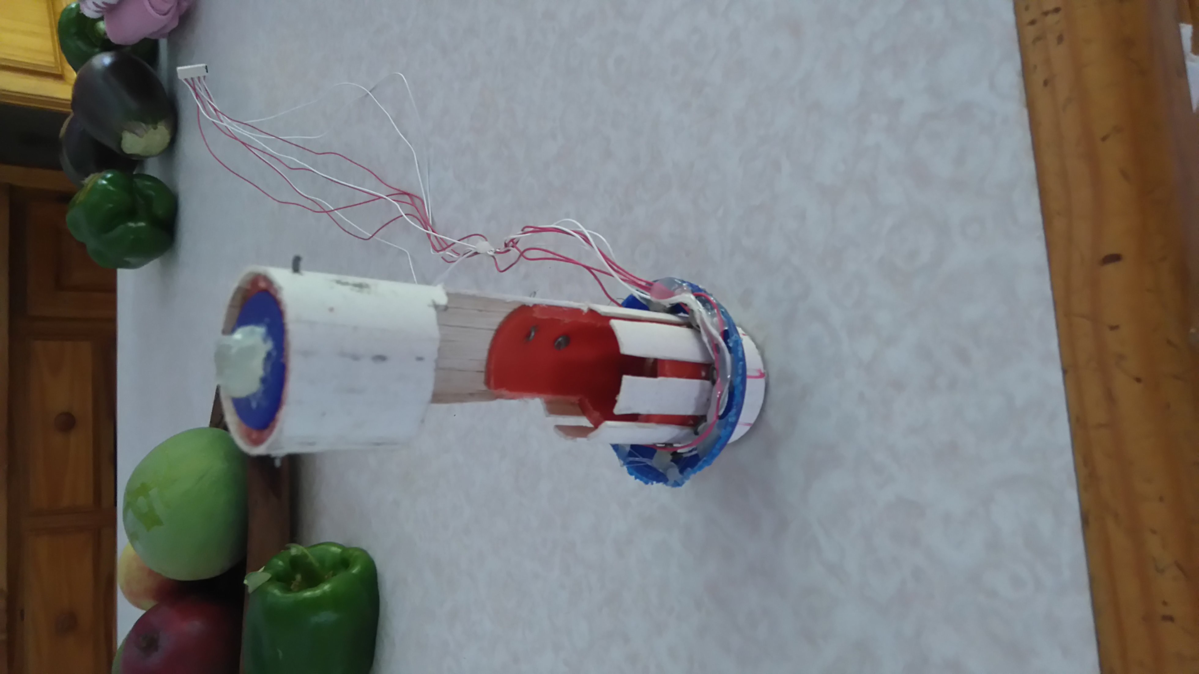
Added a second ring of the red tube, with a long section rising up. This will hold the electrodes that will turn, while the screws will be the 'stationary' electrodes. The point of this is that when I push the second piece down, it will push the screw ring down, but when it turns the screw ring won't. Since I'll only bbe turning 1/8th of a rotation, I added a spring to stop the bottom ring (the one with the screws) dropping under gravity:
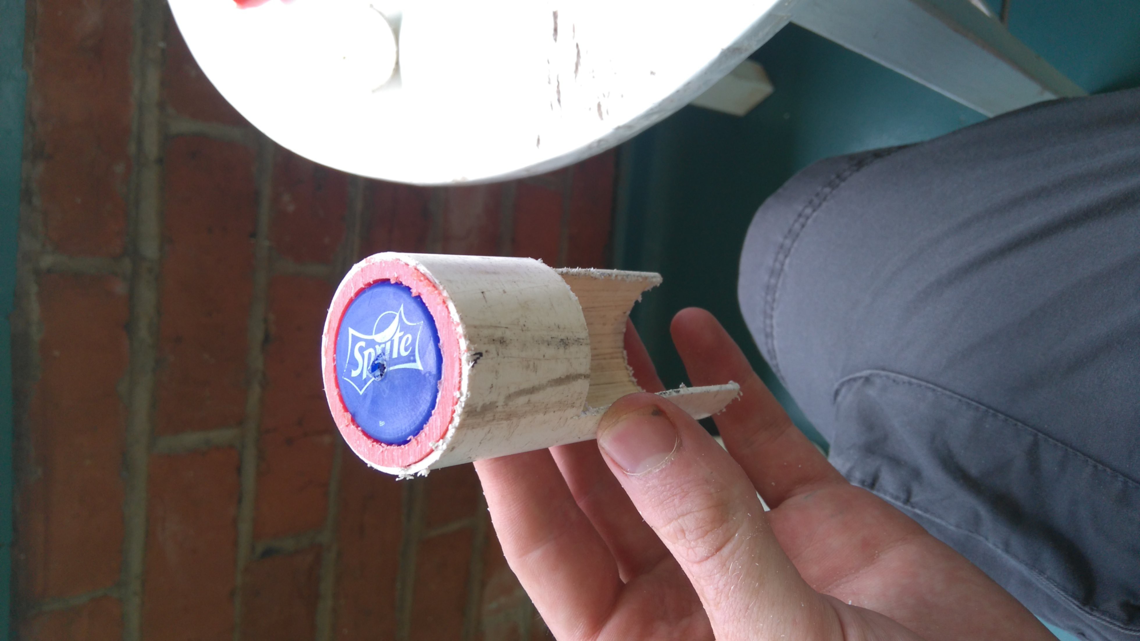
I melted some holes (with a hacked-together alcohol burner and a piece of wire) to attach a section of the wider, white PVC which will be the 'shaft' that brings the rotation from one stepper and also pushes everything down. Here's the shaft before attaching it to the motor:
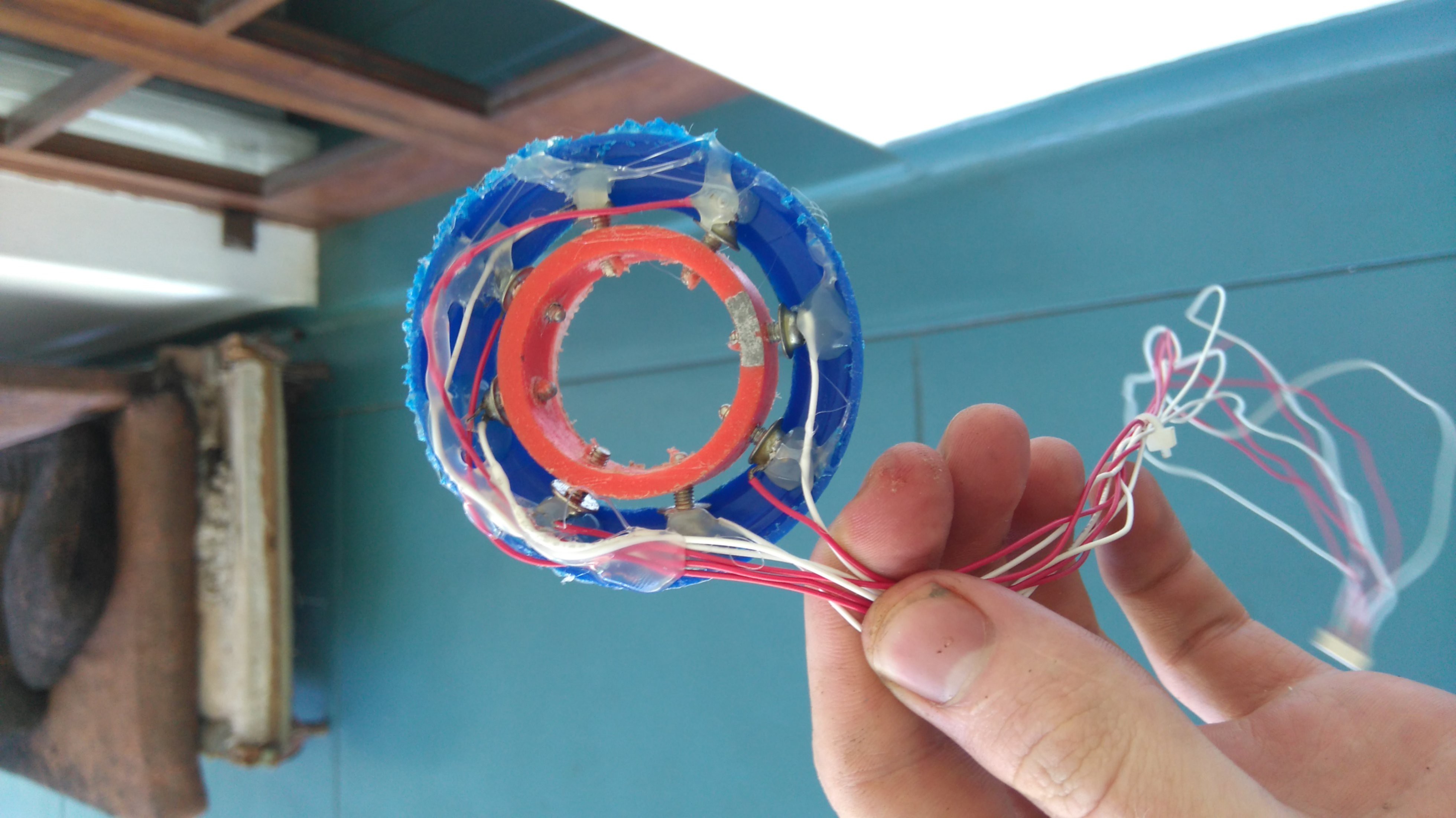
I added a ring of plastic (from a coffee tub) to go outside the PCV and hold the screws and wires in place. Oh, yes, I soldered 8 wires to the screws and hot-glued them in place. Ugly but it works:
Here it is in the PVC guide, with the shaft assembly attached:
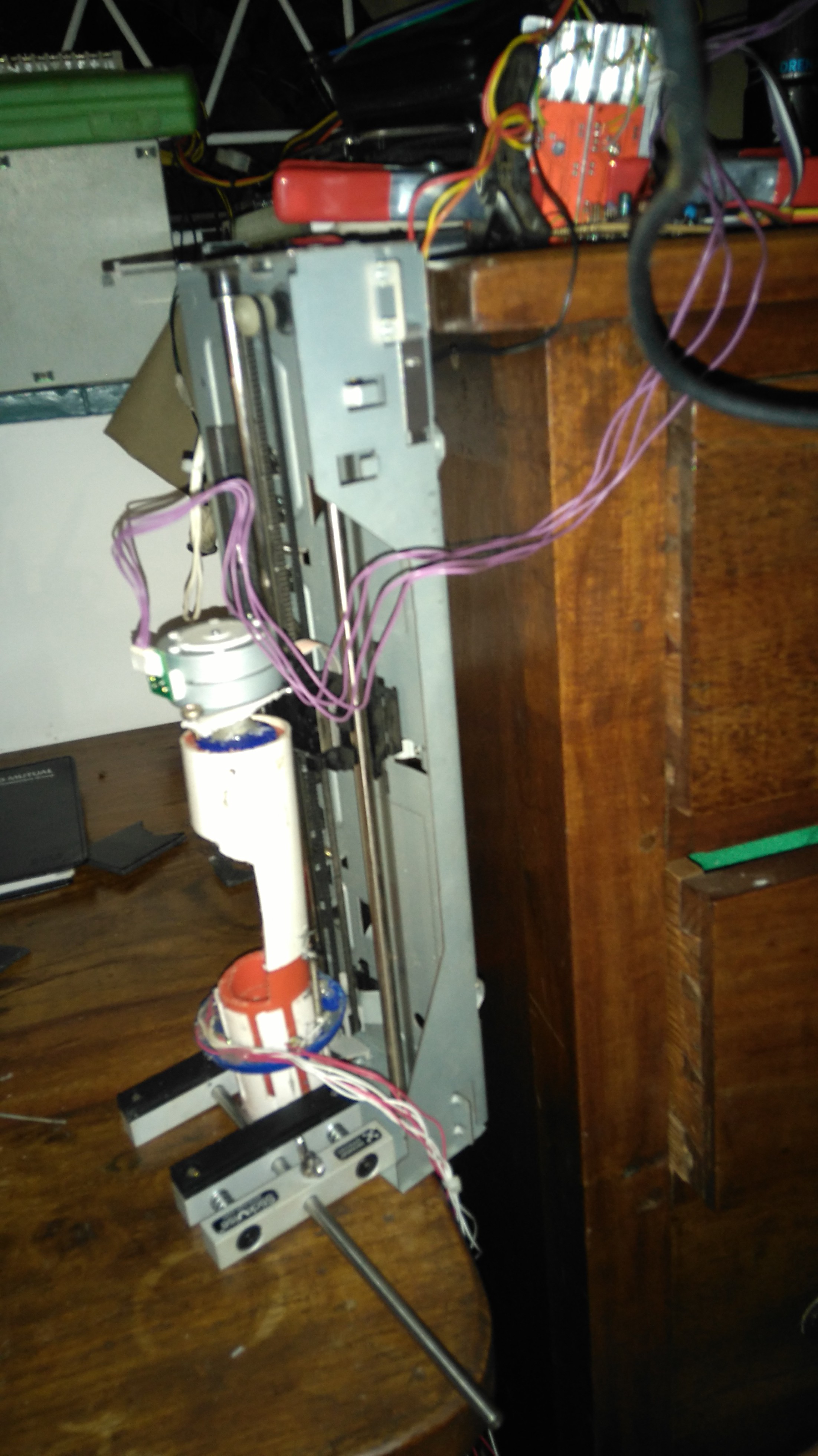
I have an axis from an old printer. I replaced the DC motor that was driving it with a stepper from a different printer, and mounted a second stepper on the sled. I have two easydrivers mounted to a big heatsink, and so I can give step+direction signals to move the sled up and down and rotate the second stepper. Here's me trying out the shaft:
And now the obligatory crappy video, where the temporary coupling between the rotating stepper and the shaft slipped off and I dropped the phone. BUT, at least you can see what's going on and it all works nicely.
Tomorrow, I will be testing out getting actual readings from the electrodes (which will involve them being in salt water) and replacing some of the hackier aspects of this build. Also, since the video I figured out why it wasn't working. I will eventually power the motors from ~9V anyway so no worries :D
 johnowhitaker
Discussions
Become a Hackaday.io Member
Create an account to leave a comment. Already have an account? Log In.