 Laetitia BEL
The PCB BOTTOM is in charge of the power distribution from the LiPo to the motors and the PCB TOP.
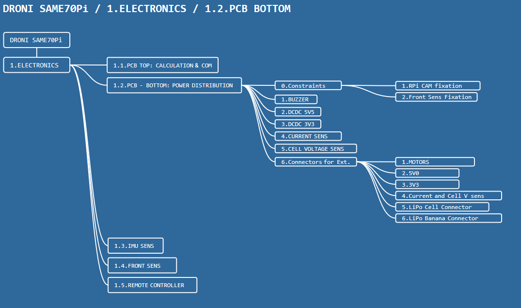
1.2.0.Constraints
I'd like to place the RPi Cams on the drone to watch down stream.
I need to place RPi Cams fixations in the PCB BOTTOM.
It shall have 3x fixations, 2x stereo and one in the middle, to have different choices.
It shall have FRONT SENS fixations, like the PCB TOP.
It shall have LiPo fixations and space.
1.2.1.Buzzer
Need to have a buzzer (loudy) in case if the user wants to make the drone buzz remotely or when the LiPo is almost empty.
1.2.2.DCDC 5V0
The 5V0 is aimed to power everything.
The converters shall provide enough power for the sensors, the SAME70 and the RPi CM.
It is evaluated approximately to 3A. (2A for the compute module)
1.2.3.DCDC 3V3
The 3V3 will be used to power the SAME70 and some sensors.
Power estimated to 1A.
1.2.4.Current Sensing
The PCB BOTTOM shall have a current sensing.
The idea is to measure the current provided by the LiPo to estimate the remaining power or simply for monitoring.
1.2.5.LiPo Cells Voltage Sensing
To have an accurate estimation of the remaining power and speed of discharge, we can measure the voltage of the cells of the LiPo.
The voltage of each cell of the LiPo is sent to the TOP PCB (SAME70-M2) .
1.2.6.Connectors for External Modules
The PCB BOTTOM shall have the following interfaces:
- soldered banana wire for the 4x motors/ESCs
- 5V0 power source to the TOP PCB for the 1V8 2V5 converters + the sensors
- 3V3 to power the SAME70 and the sensors
- voltage to measure the current to SAME70-M2
- voltages to measure the cells of the LiPo to SAME70-M2
- soldered banana wire for the LiPo Battery
Discussions
Become a Hackaday.io Member
Create an account to leave a comment. Already have an account? Log In.