 Laetitia BEL
I didn't expect from the remote controller to be complex, in the idea it was simple, but when you put the content on paper you realize that it will be as complex as the TOP PCB.
1.5.0.Constraints
Need to have a placement for an LCD screen. In case if the user wants to make local extra hack with a display.
Shall have the neck string attachment.
1.5.1.LEDs/Buttons
Will have a bunch of buttons and LEDs. But mainly:
- to monitor radio connection status
- to turn on the drone
- to arm the motors
- to make buzz the drone
- ...
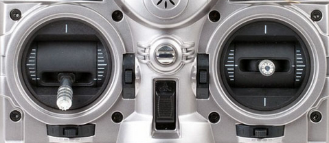
1.5.2.Analog Stick
The idea is to have the same analog sticks as TRANIS.
1.5.3.xBee for telemetry
It will have a xBee for telemetry, that communicates with the SAME70-M2 in the PCB TOP.
1.5.4.xBee for real time control
We use a seperate xBee for real time control
1.5.5.SAME70-R1 for real time control
I can use only one microcontroller, but the idea is to have full dedicated computing unites for more flexibility and availability.
No headaches with cycle constraints or code optimization or tasking.
1.5.6.SAME70-R2 for telemetry
It will communicate with the telemetry part of the PCB TOP
It will have the possibility to send data to a computer if connected to the uUSB;
1.5.7.Connectors for external interfaces
uUSB for programming the SAME70-R1 and R2
The uUSB used for programming the SAME70-R2 will be used to communicate with the computer.
There will be connector for the FR'SKY analog sticks
A connector to link the remote controller's PCBs.
Discussions
Become a Hackaday.io Member
Create an account to leave a comment. Already have an account? Log In.