Close
0%
0%

AVR-ZIF Programmer

An AVR Programmer based on USBasp which uses a ZIF-Socket for Programming.

Similar projects worth following
An Universal AVR Programmer with a ZIF-Socket and ISP Header.

Features:

  • based on USBasp by Thomas Fischl
  • ISP-Connector on PCB
  • can Program many different AVRs:
    • ATMega 164/324/644/1284/16/32
    • ATMega 8/48/88/168/328
    • ATTiny 2313/4313
    • ATTiny 26/261/461/861
    • ATTiny 25/45/85/13
  • socket for Crystal/active Clock Source
  • main AVR can be updated/reflashed via USB
  • LED shows data transfers

AVR-ZIF-Prog.pdf

Schematic

Adobe Portable Document Format - 114.88 kB - 03/18/2017 at 14:22

Preview

  • 1 × ATMega8PU The MCU, that controls everythinh
  • 2 × LED for showing Data Transfer
  • 1 × ZIF40 Socket The Socket for the AVR, that should be flashed
  • 1 × Polyfuse 500mA Limits the USB Current, so that it doesnt damage your PC
  • 2 × 100nF SMD 0805 For Power Filtering

View all 18 components

  • It works!

    Jan B.03/18/2017 at 22:47 0 comments

    Hello everybody,

    after I fixed some broken connections on my self-etched PCB, it seems to work so far I could test. I tested an ATTiny 13, an ATTiny2313 and an ATMega8, so it should work with their respective MCU-families, too. I could not the ATMega 16 and ATTiny 26 family (but I think they should work), so if anybody rebuilds this project and test these MCUs i would be pleased when you write a comment.

    I have released my design files under the CERN OHL v1.2 License, you can find them together with my modified bootloader and firmware code in this (https://github.com/jbtronics/AVR-ZIF-Programmer) GitHub repo

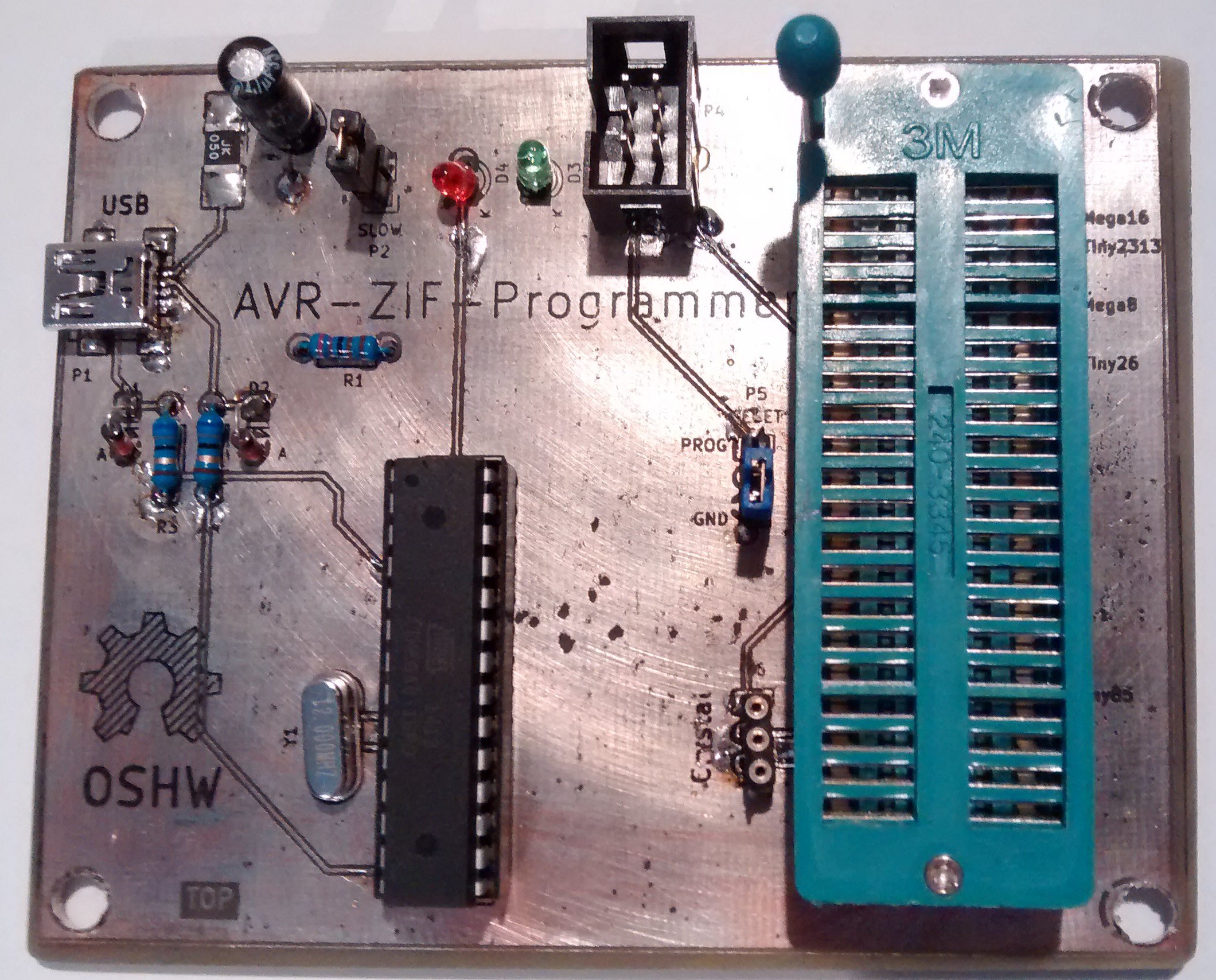
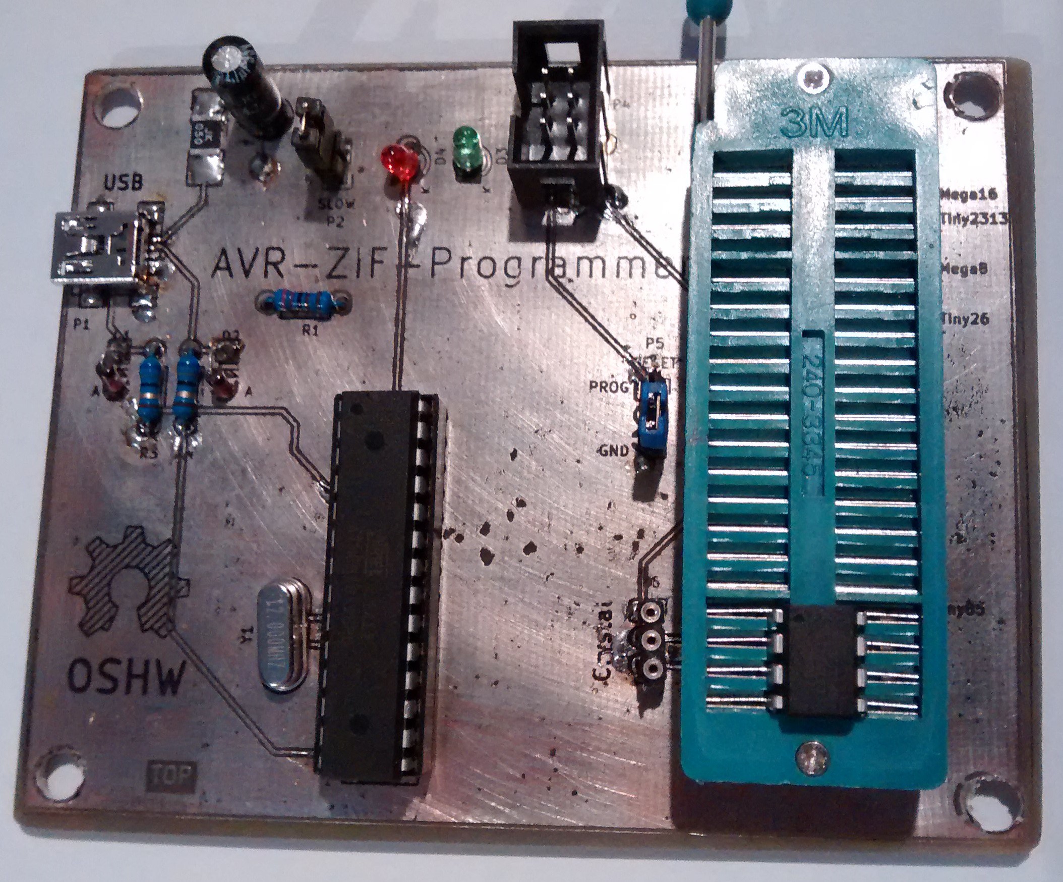
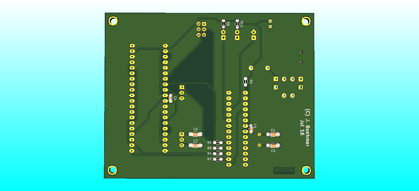
    Finally some images of my board. It is self-etched with Sodiumpersulfate using the toner-transfer method. With the same method i put some silkscreen like print on the board. Additionally the board was tin-plated using some fittings solder paste:


  • [Quick Updates] Renderings

    Jan B.08/05/2016 at 00:03 0 comments

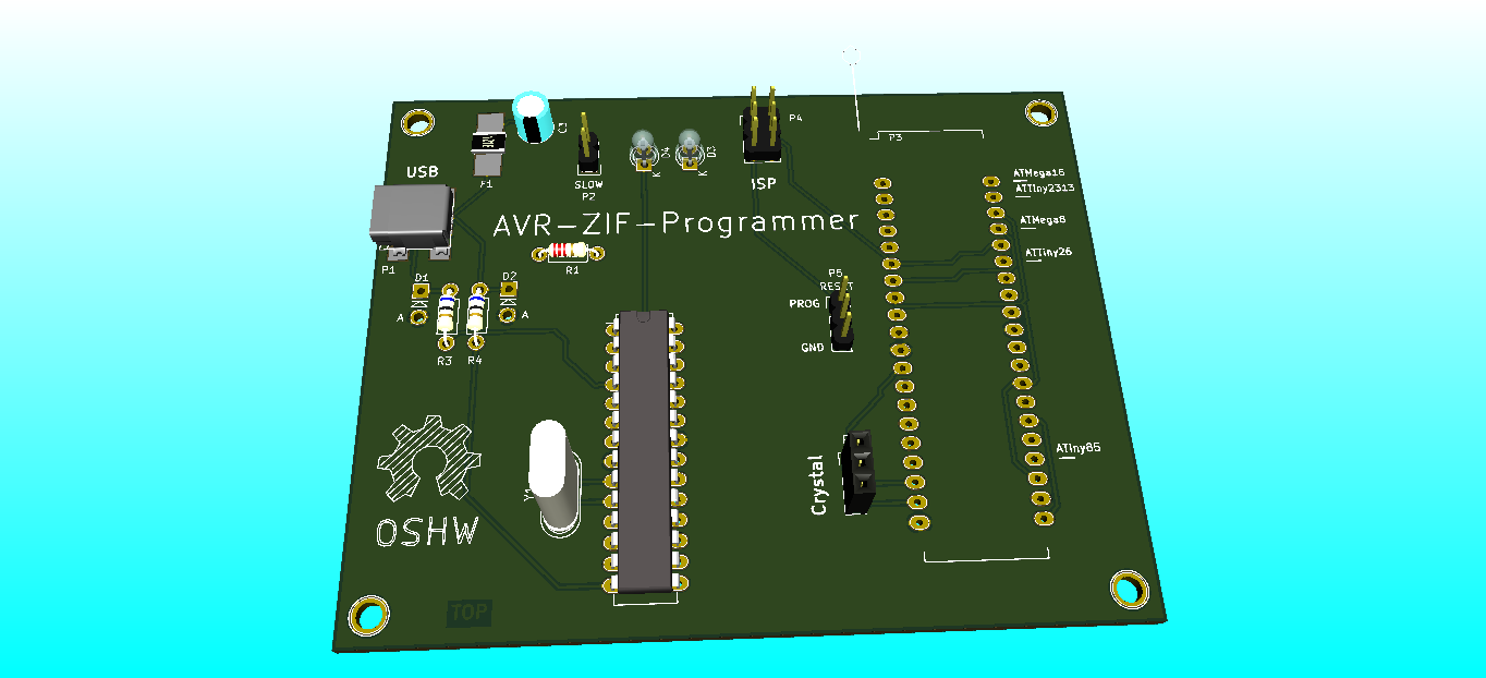
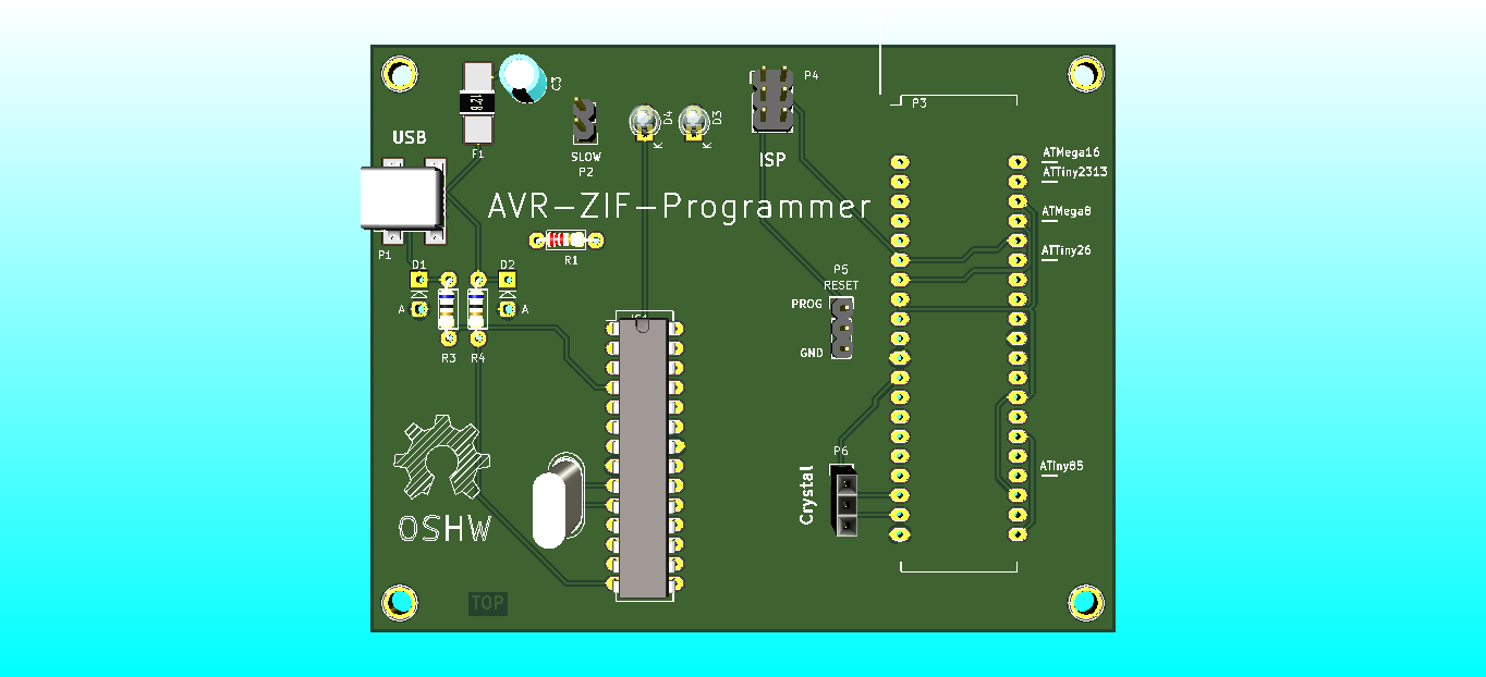
    Here are some Pictures of the PCB that I have rendered in KiCAD.

    In the next few days I will etch the PCB, build it and test it. I will keep you updated.

  • Files are uploaded!!

    Jan B.03/11/2016 at 15:54 0 comments

    Hi,

    I have not the time to test my Design yet, so I do not know if it really works ( but I think it will :) ), but I upload my KiCAD Design already ( They should be in the Files Section now).

    When someone finds mistakes, have improvements, or even build the Programmen then write it in the Comments.

  • Schematic finished

    Jan B.02/04/2016 at 19:46 0 comments

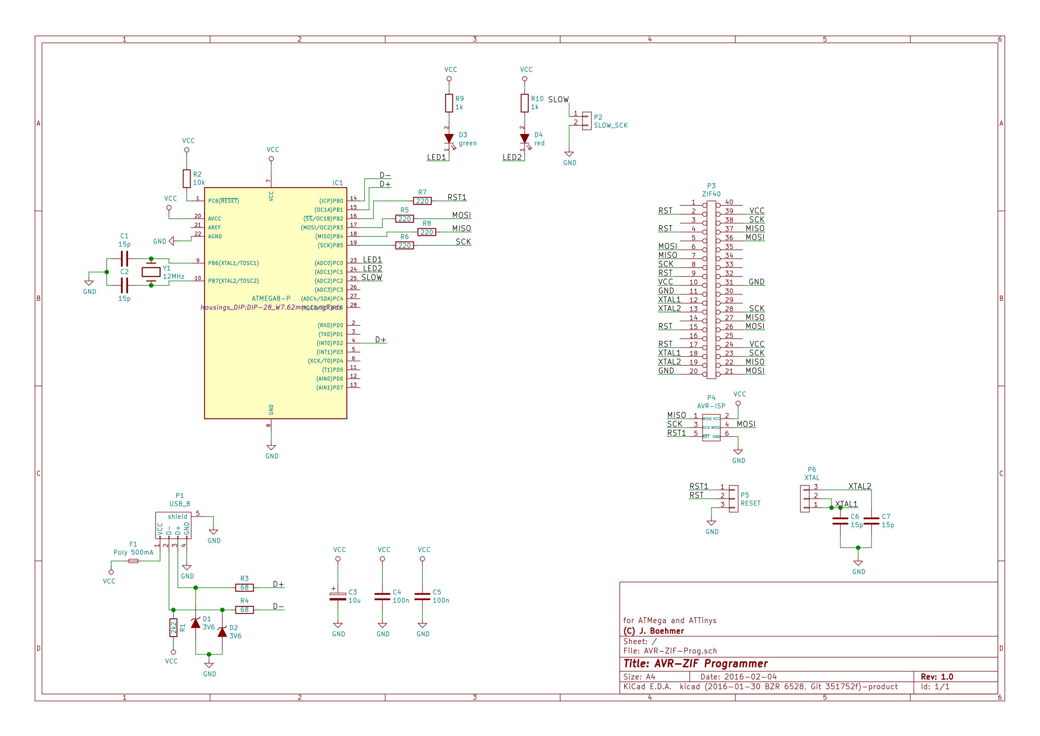
    Finally I have finished the Schematic for the Programmer and have done the assignment of Footprint to the single schematic symbols.

    Now I have only to create the PCB and then test it.

    Here is the Schematic already:

View all 4 project logs

  • 1
    Step 1

    Use the Layout files to order a PCB or made one by yourself.

  • 2
    Step 2

    Solder all components on it, except the Mega 8. I suggest to solder a socket for it instead. So you can replace it later (in case of wrong programming the "Master" CPU")

  • 3
    Step 3

    Put your Mega8 (or 88/168/328) in the ZIF socket in the right position for Mega8. Put the RESET-Jumper P5 in the Position PROG.

View all 7 instructions

Enjoy this project?

Share

Discussions

Ember Leona wrote 03/19/2017 at 01:23 point

Hi I had an idea for slot loading cartridges and ZIF alternative. The metal should clamp down like a guitar capo. The game cart or chip is inserted then a slot like level slides the wires in place. 

  Are you sure? yes | no

Similar Projects

Does this project spark your interest?

Become a member to follow this project and never miss any updates