WHO:: We are 3 dudes from California with backgrounds in HW and SW engineering. We enjoy building and hacking things for fun.
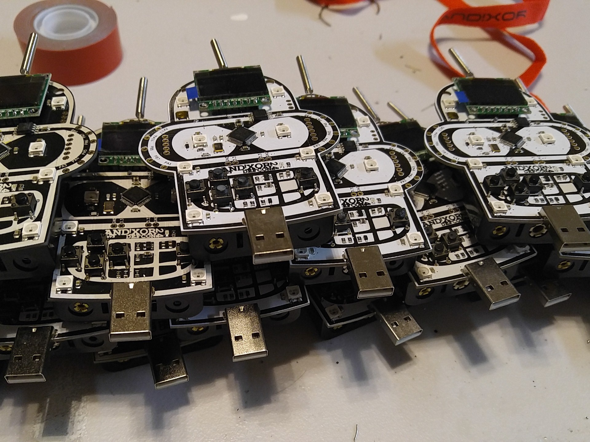
WHAT:: We built a hackable, open badge for use at DEFCON 24 in Las Vegas and any other conferences in the future. The badge also serves as a dev board for hardware developers of any experience level from novice to expert sorcerer.
WHY:: The purpose is to put some really awesome hardware around the necks of a bunch of hackers and see what they come up with. We hope to encourage others to make use of the badge and come back with their own flavor in years to come, AND to promote embedded development across the community.
HOW:: Pure internet science. We've developed algorithms which calculate the spin rate of cat quarks for generating our ssh keys at a rate of (P+9)/((# of blackberry users)^2), where P is the probability that a cat will leave a house when a door is opened for them.
WHERE:: Paris Hotel, Las Vegas
WHEN:: August 4th - August 7th, 2016
EXTRAS:: We are spending our free time and money outside of our busy work schedules to develop this from 3 separate locations across California. So we are definitely open and encourage feedback, suggestions, and features to be added onto the badge. If you complain that there are not enough blinky's happening then you are welcome to build your own. Feel free to Leave your comments below if you have questions, concerns, comments, philosophical statements, haiku's, or send us a tweet...that works too.
Twitter:: Check out AND!XOR, our official twitter account on twitter for daily and often hourly updates of the badge process.
 Zapp
Zapp
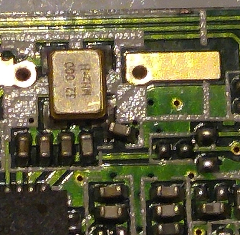
 Notice the capacitor is dislodged from one of its pads.


This is just some notes from my build of the Bender badge.
You can get the circuit boards from https://oshpark.com/shared_projects/SZuuWLvi
Parts: There is a list here, but there is missing a 100 ohm resistor, the board shows 18pf caps for the clock (list shows 22pf), and one other detail: Where do all the parts go? What I did to figure this out was to use the schematic, pictures, and this: https://hackaday.io/project/9064/gallery#770ed9cfb15937bacc7f50ca59da9091
Alightment of the LED, the green end goes towards the top of the board. I also came up with this to help: http://imgur.com/5Q0Ih8P (fixed thanks to @yaakov_g)
Check for bridges when you solder in the cpu, then check again, oh yeah CHECK FOR BRIDGES! All angles, magnifing glasses, flashlights, whatever it takes. My first cpu died when the magic smoke left it because of a bridge.
Where to get the parts? I used Mouser and Digikey for the majority of the parts. The radio and usb connector came from Amazon, the display, antenna, and reset button came off of ebay. The tactile switches came from my junk box.
Assembly:
I divided the board in to three areas: the mouth, eyes, and head. I put the surface mount components on the mouth and head first. The cpu was next, followed by the rest of the eye section. The tilt switch and radio were next, then the display and tactile switches. The usb connector was last, for me since I couldn't find an exact match for what was used on the original, I removed the tabs that were on mine and used a pin to tie one side of the connector to the board for stabilty. Last part was the battery holder.
I also put a set of header pins to make selecting the programming mode easier, for everyday use, temporarily jumpering the pads should be good.
So you checked 348 times to ensure there are no bridges, put the batteries in, if there is no smoke, you most likely did good :)
Programming:
I used one of these: CP2102 Module STC Download Cable USB 2.0 to TTL 6PIN Serial Converter For STC (https://www.amazon.com/gp/product/B009T2ZR6W)
It just so happens it will plug right into the programming header on the board, I held it in place when I did the flashing of the bootloader. Janky? Yes, but it worked just perfect. I used a ubuntu vm to program the board, it was easier to just use the linux tools that were provided that way.
Githubs:
https://github.com/ANDnXOR/ANDnXOR_DC24_Badge
https://github.com/rogerclarkmelbourne/Arduino_STM32
Bootloader: ANDnXOR_Badge-Bootloader.bin found in the Provision directory
Using the CP2102 and having the top two pins of the boot pins jumpered or shorted will get you in to the mode so you can flash the bootloader.
You can find stm32flash in the tools directory for you os (ie Arduino_STM32/tools/linux64/stm32flash/ for 64bit linux).
./stm32flash -w ANDnXOR_Badge-Bootloader.bin /dev/ttyUSB0
Badge code: ANDnXOR_Badge-Human.bin found in the Provision directory
I moved my jumper to the middle and lower pin on the boot pins when I did this part. The dfu-util program can be found at in the tools directory for your OS in the dfu-util directory. If you are using virtualbox, you will need to "connect" the badge usb device to the vm. If you can't see the device (check device manager on windows or if on a linux box, check dmesg), check your board, check the resistors near the usb connector (that was my issue, the 1.5k wasn't).
While connected to USB:
dfu-util -D ANDnXOR_Badge-Human.bin -d 1eaf:0003 --intf 0 --alt 2
NAND load: ANDnXOR_Badge-Flash.bin found in the Provision directory
This is also done while connected to USB. It was very slow for me, you should see a percentage progress counter when it is working. It took a couple of tries for me to get it to run, but it finally did.
./flashdata.sh /dev/ttyACM0 ANDnXOR_Badge-Flash.bin
I had some help with getting this programmed and debugged from @ANX
I have to say it is an awesome badge, I had it with me at DerbyCon this weekend and had at least 8 or 9 people ask me about it, how to get it, and/or how to make it. Great job guys, can't wait to see next year's badge. One thing, please add a power switch :P