 deʃhipu
After some cosmetic touches, I'm finally happy enough with the first version of the PCB for this robot. It looks something like this:
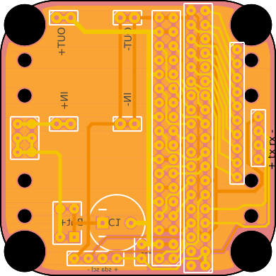
The Fritzing file is in the repository, and the Gerber is available for download. I used a new approach for the servo sockets -- since the Pi Zero is going to be plugged as a second layer, we don't really have enough space for the usual servo sockets. So I used one long header with angled pins -- the servos plug in two rows into that, fitting between the Pi and the board.
Other than that, the board has the serial and I²C pins broken out, and also a header for all the pins that are not used for controlling servos. There is also a jumper in there, for disconnecting the servo power from the Pi -- so that we can power the two from two different sources if we need to.
The usual holes, as in Tote, are for attaching the servo horns for the legs.
Discussions
Become a Hackaday.io Member
Create an account to leave a comment. Already have an account? Log In.