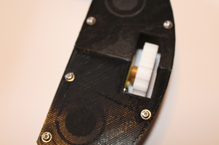
Based on the results of the first motion test, I made several tweaks to the chassis for version 0.2.

- As I stated in the motion test, ground clearance was a big issue that caused problems on carpet. I don’t know the general measurements for carpet thickness, but the medium-pile carpet in my apartment was tall enough that the chassis was lifted up and the wheels couldn’t get a good purchase on the ground. This prevented the robot from moving at all. I’m hoping 7.5mm will be enough ground clearance, but I’ll find out once I do another motion test.

- I added a side wall to the robot to increase stiffness. With the flexibility of PLA, the middle of the robot sagged and as a result the center dragged on the ground. Adding an extra dimension to the robot in the form of a wall helps with stiffness and prevents most sagging. My first attempt at this was in the form of an integrated side wall, allowing the entire thing to be printed in one piece. This, however, turned out to be a bad idea. With the wall in the way it was extremely difficult to get tools into the chassis to add in the vitamins (e.g. motors, casters, etc.). DFM is important! So instead of integrated walls I went for a more modular approach.


- The base is much like it was before, flat and simple, but I’ve added holes for attaching the side walls as separate pieces. The side walls then have right angle bolt hole connected so the wall can be bolted on to the base after everything has been assembled.

- One thing I don’t like about this method is that all of the bolt heads that will be sticking out of the bottom of the chassis. I’d like to go back at a later time and figure out how to recess the bolts so the bolt heads don’t poke though.
- With the stiffness added by the side wall I decided to decrease the thickness of the chassis base and wall from 2.5mm to 2mm. This results in saved plastic and print time.
- Adding the side wall had the downside of interfering with the sonar sensor. I’m not too familiar with the beam patterns of the HC-SR04 module, but I didn’t want to risk the wall causing signal loss or false positives, so I moved the distance sensors outward so the tip of the ultrasonic transducers are flush with the side wall. Unfortunately, due to the minimum detectable distance of the sensor, this means that there will be a 2cm blindspot all around the robot that will have to be dealt with. I’m unsure of how I’ll deal with this at the moment, but I’ll most likely end up using IR proximity sensors or bumper switches to detect immediate obstacles.
- Other than the above changes, I mostly just tweaked the sizing and placement of certain items to optimize assembly and part fits.
This is still very much a work in progress and there are still several things I’d like to add before I start working on the actual vacuum module, but I’m happy with the progress so far on the navigation chassis and think it’ll be complete enough to work as a test platform for navigation and mapping.
 Keith Elliott
Discussions
Become a Hackaday.io Member
Create an account to leave a comment. Already have an account? Log In.
very nice design! May I ask how are you planning to build the vacuum module? :)
Are you sure? yes | no
Surely! I plan on 3D printing a dirt bin that plugs directly into the negative space in the navigation module. For starters I'll put squirrel cage fan from Sparkfun (https://www.sparkfun.com/products/11270) to suck dirt into the bin. Once I get that working I'll take a look at adding a beater bar in as well.
Are you sure? yes | no
That's cool! Thank you :)
Are you sure? yes | no