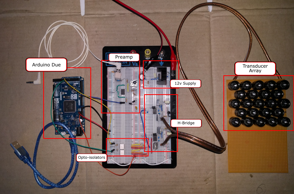
I finished step 1 from my plan.

It works! The speaker shows a directional effect, and it's quite loud, at least in my work area, with the supply cranked up to 30V.
System Design
This is the design for the signal processing path:

- Input signal passes through an op-amp to amplify it to the 0-3.3v range that is suitable for the Arduino Due's ADC.
- The ADC does what is supposed to do: it converts the analog signal to a digital one. The Due has a 12bit ADC. There's a little noise, which, as far as I can tell limits its effectiveness to somewhere between 9 and 10 bits. That's OK because the later PWM stage only has a 10-ish bit resolution.
- The Arduino's PWM generator is set to produce a 40kHz waveform. Every 1/40,000th of a second, the Arduino sets the PWM duty cycle based on the reading from the ADC unit.
- The output of the PWM is used to drive an H-bridge, effectively amplifying the few milliamps at 3.3v from the Due to transducer driving level.
Schematics
I'd like to post more about the individual sub-systems, but for now, here are schematics covering the bulk of the electronics, and which may help explain a little more. The schematics are online in EasyEDA.
Preamp

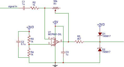
The design was somewhat inspired by the ElectroSmash PedalSHIELD, but greatly simplified. Greatly. It was just much easier to do a single-channel inverting design rather than a dual channel design, and frankly, I don't really understand the feedback mechanism used in the ElectroSmash pedal. I did, however, copy the input protection mechanism of a 4k7 resistor and reverse biased schottky dioides to ground and 3.3v.
This circuit seems a little noisy. I need to investigate that further. In a future iteration, I'd like to try generating a negative supply rail, as the PedalSHIELD does. This will allow the use of a higher precision op-amp.
The preamp is powered from the Arduino. In the breadboard prototype, the Arduino is powered by the USB port.
H-Bridge

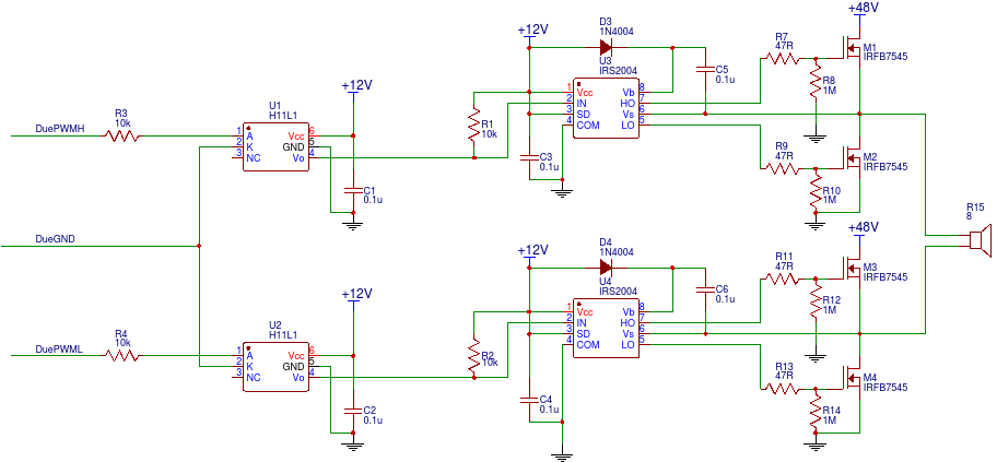
This is a fairly standard H-Bridge circuit. Let's review it from the left side (input) to the right side (output).
The Arduino PWM generator produces complementary outputs PWMH and PWML. The way this is configured, one is simply the inverse of the other. It would be possible to just use one PWM output and invert it, and I may try that in future.
The signals pass into two H11L1 opto-isolators. I decided to use opto-isolators after toasting two Arduinos in earlier experiments. Internally, they have an open collector transistor which turns on whenever the input current is high enough, and turns off whenever the input current drops sufficiently. Because the H11L1s cannot provide current the output is pulled high by R1 and R2. The effect of this is that the input signal from the Arduinos is inverted, amplified to 12V and delayed by 1 microsecond.
The H-bridge is driven by two IRS2004 half-bridge drivers. These contain the logic to alternate between high and low sides of a half-bridge, ensuring that the supply voltage and ground are never connected together. They also are able to use an external diode and capacitor to generate the voltage needed to drive the high side MOSFETs efficiently (48V + 12V in this case).
The opto-isolators and half-bridge drivers cannot use the 48V supplied to the speakers - it's too much. The H11L1s have a 16V maximum and the IRS2004s have a 10V minimum, so on the breadboard prototype, an LM7812 is used to derive 12V from the bench power supply (not shown).
The prototype uses four IRFB7545 N-channel MOSFETs. These have cause less than 0.1 volt drop at 10 amp load, which means < 100mW power dissipation even at that point. They run very cool. 47R resistors protect the drivers from the gate in rush current, and 1M resistors pull the gates down to zero in the absence of drivers. The transducer array is connected directly across the bridge.
At this point we have amplified 3.3v at a few milliamps to potentially 48v at tens of amps. Not bad.
Confessions and Next Steps
Actually, this is my second prototype. The first one worked, but I was unhappy with several aspects of it and so decided to do it again from scratch. This new one:
- Pre-amp is completely reworked, including better input protection.
- Opto-isolators protect the Due from higher voltages.
- The breadboard is much more nicely laid out.
- Drives a larger array of transducers.
Next up, will be to move away from the bench power supply. I have two 48V, 10A power supplies ready to unpack and wire up to connect to the mains.
 Alan Green
Discussions
Become a Hackaday.io Member
Create an account to leave a comment. Already have an account? Log In.
Interesting project and really well documented. May I ask where you sourced the transducers you're using from and how much current they drew? Was thinking of trying this with the transducers on the HC-SR04 Ultrasonic Rangefinders.
Are you sure? yes | no
A very interesting project! You should attempt to upload a video indicating the power and directionality of the speaker. I'd like to see if I can make a simple version of what you've done :) Well layed out too.
One other thing. Do you think it is possible to develop a speaker that does this without a microcontroller handling the ADC conversion to a duty cycle modification of your 40KHz PWM signal?
Are you sure? yes | no