Close
0%
0%

eXaTutor

A Raspberry Pi-based device that helps you learn music.

Public Chat
Similar projects worth following
EXaTutor aims to help you learn music. The goal is to provide a complete set of tools that teach rhythm, notes, hands coordination, and many other very important techniques that are essential when learning music.

The idea is to make an easy to build system with a very intuitive touchscreen interface at a reasonable price.

The hardware consists of a Raspberry Pi, its official touchscreen and sensors that are connected to an analog to digital converter. As for the software, it is written in C++ and its graphical user interface is based on Gtk. It is thus usable on most Linux distributions, including Raspbian (Stretch or newer).

Presentation

It usually takes years to master an instrument, and it takes a lot of time, effort, and practice.
Although it is very difficult to pick the right instrument, learning music the right way can certainly help.

Music can be very theoretical and appear complicated to kids. However, kids usually love to hit things and make noise, sometimes even with a surprisingly very good rhythm and melody, and those two elements are key. It is not a coincidence if most famous music video games consist in pressing the right button at the right time (or hit the right pad at the right time). Showing the notes that need to be played and scrolling them in sync with the music is very intuitive and efficient. 

The goal of eXaTutor is to take the idea of rhythm games one step further by turning a rhythm game into a training tool. On the one hand, the user interface will be based on those of video games, on the other hand, data will be collected in order to create training programs tailored to the user's experience. The software will give the user all details about what and how he or she can improve.

How it works

One of the easiest instruments to introduce kids to music seems to be the xylophone. Perhaps because they can hit things, make music, and have fun all at the same time. In that regard, eXaTutor's official version will be a xylophone. Of course, it will remain possible to modify the hardware in order to turn it into any instrument.

The software is what will make eXaTutor great. It will provide a visual way of learning music, teach the good techniques and guide the user. It will adapt itself to ensure the best learning curve possible and find the right balance between practice and fun, in order to keep the user motivated.

Hardware

EXatutor uses a Raspberry Pi and its 7" official touchscreen as a user interface. Sensors are connected to an analog to digital converter, which is connected to the Raspberry Pi. As for the system's fabrication, it will be made as easy as possible.

Software

The software is being designed, and will rely on libeXaDrums in order to offer the best performance possible. Gtkmm will be used to program the user interface, and make as user friendly as it can get.

  • 1 × Raspberry Pi 2B, 3B or 3B+
  • 1 × Micro-USB PSU (2A or more)
  • 1 × 8GB SD card
  • 1 × Raspberry Pi's official 7" Touchscreen
  • 1 × RasPiO Analog Zero http://rasp.io/analogzero

View all 7 components

  • Piezo To ADC Voltage Mapping, The Easy Way

    Jeremy05/25/2018 at 05:42 1 comment

    In order to read the piezos voltages in real time, we are going to use a RaspIO Analog Zero board. The board uses an MCP3008 analog to digital converter (ADC) that has an input voltage range of 0 to 3.3V.

    As a consequence, we need to map the output voltage of each piezo sensor to the 0-3.3V range. There are several ways to do that, but we're wondering here what's the easiest solution. And by the easiest, we mean the solution that requires the less components.

    First of all, we need to remember how a piezo sensor works. In short, we could say that a piezo sensor converts a mechanical strain into a voltage. But what happens when this voltage source is connected to a load? 

    Like any voltage source, a piezo sensor has its limits, and can only deliver so much current when connected to a resistor. When the load is too small, the current going through it becomes too high for the piezo to maintain a high voltage, thus the voltage decreases.

    Does that means that connecting a small resistor between the legs of a piezo decreases its output voltage? Yes, but not only: it also modifies its response, but in our case, we will assume that this effect is not a limitation as we only need to detect voltage peaks.

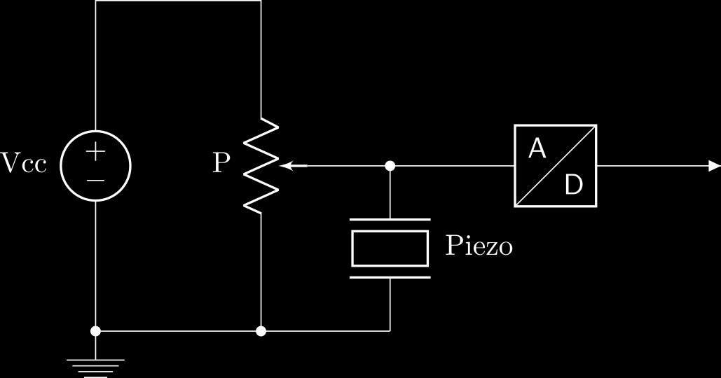
    Because the piezo's output voltage undergoes positive and negative peaks, we need to set a resting point of 1.65V (3.3/2 V) to be connected to our ADC. That can be done using a potentiometer, like so: 

    Let's consider a 10k potentiometer. In that case, if we use a 5V power supply, the potentiometer acts as a voltage divider:  

    Since we know that R1 + R2 = P = 10kΩ, if we want Vout to be 1.65V, we need R2 to be 3.3kΩ:

    So by using a potentiometer, not only we've managed to set a 1.65VDC input voltage at the input of the ADC, but we've also added a load (R2) in parallel with the piezo. The sensor is thus seeing a resistive load of 3.3kΩ (if we neglect the input impedance of the ADC), which means that its output voltage will be a lot weaker than if it was directly connected to the ADC.

    My first experiments show that, under normal conditions, no damping of the piezo is required. But in order to prevent the voltage from going above 3.3V or below 0V, I'm probably going to dampen it a little bit.

    Sounds that I'm lucky (or maybe it was all planned), as there is a potentiometer board that has eight 10k potentiometers. I've already bought one, which I found on Mouser (reference 932-MIKROE-316).

    Next time we'll see how to use this board to connect our 8 piezos to the MCP3008.

  • Here are the sensors!

    Jeremy05/01/2018 at 14:15 0 comments

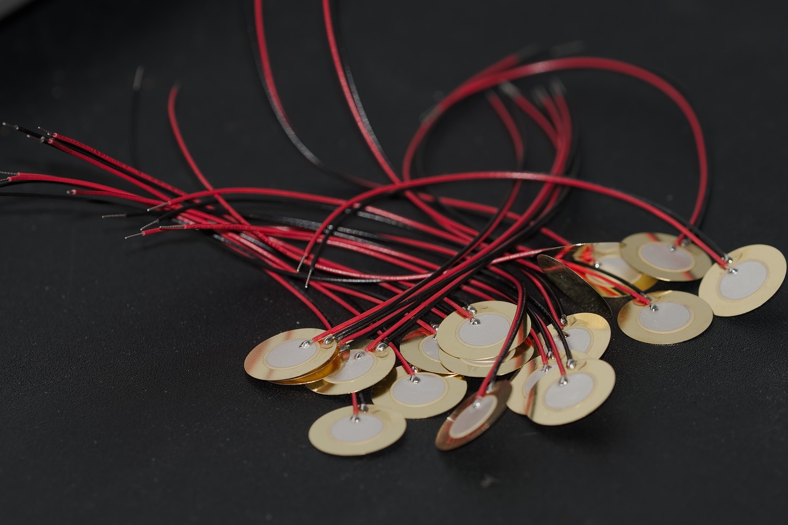
    I ordered 20 of those piezos: http://www.puiaudio.com/product-detail.aspx?categoryId=5&partnumber=AB1541B-LW100-R. I got those particular ones for two reasons: PUI Audio is usually pretty good quality, and they are small (15mm diameter).

    Here's a picture of most of them:

    They are exactly 15mm wide, which is perfect. Another consequence of their small size is that their output voltage is lower than bigger sensors. That's going to be useful in the future, but I'll explain why in another post. They are also pretty cheap, as I got them on Mouser (ref: 665-AB1541B-LW100-R) for $22 ($1.10 a piece).

    Well let's get to work now!

  • Initial Project Plan

    Jeremy03/18/2018 at 16:48 0 comments

    Here's a list of things that need to be done for the project:

    • Add build instructions.
    • Develop the software and put it on Github.
    • Make the device's fabrication easy: make it out of cardboard.
    • Choose the sensors (piezo).
    • Design the sensors interface circuit, and make it.
    • Design the graphical user interface.
    • List of features (non exhaustive): 
      • Visualize and scroll notes in real-time (rhythm games style).
      • Progressive training mode which adapts itself to the player's level.
      • Import and export music sheets.
      • Possibility to manually change the tempo, and add a click sound.
      • Training mode that evaluates and rate the user's skills: jitter, velocity, etc.
      • Manage chords, and complex melodies.
      • Save playing stats, and show progression, parts to improve, etc.
      • Advanced training exercises to improve specific skills: velocity, rhythm, etc.
      • Rating system that is saved every time you play.
      • Complete stats logs.
      • Compatible with all the eXa software suite to allow music composition.
      • Probably some other things to add...

View all 3 project logs

Enjoy this project?

Share

Discussions

Similar Projects

Does this project spark your interest?

Become a member to follow this project and never miss any updates