 Arduino Enigma
While waiting for the V1 PCB to come back from the fab, I play with the concept of designing a slimmer version. Since the original calculator is 110mm x 50mm, to have the same proportions in a 100mm board, the width would have to be 46mm.
Each display is 15mm wide, all three would take 45mm, so this seems plausible. The display resistors are tentatively arranged in a 45 degree angle.
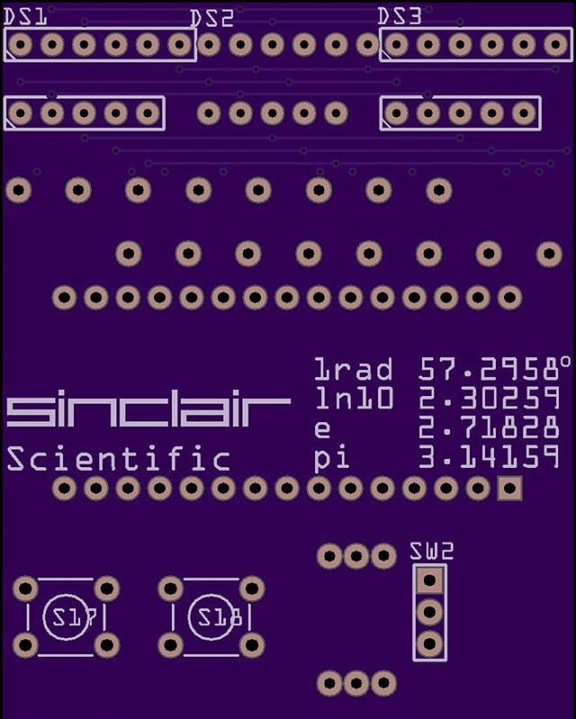
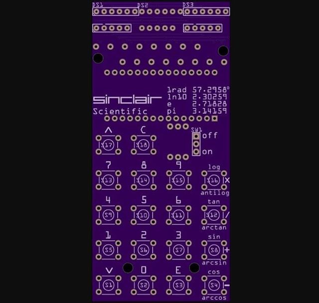
An attempt is made to have the separation between the displays and the keyboard resemble the actual calculator. The key spacing in the X and Y dimensions is also calculated to match the look of the original.
In the end, this is only a proof of concept that is never fully routed or sent to production. I wanted to wait until the first version is up and running to find out where the problems will be before designing another board. This proves to be a good decision.
Retrospectively, here are the problems this board was going to run into:
1) A battery holder for 4 AAA batteries is at a minimum 48-49mm wide. The board needs to be at least this width to conceal it in the back. The original calculator uses some surface mount battery contacts that I have not been able to find a satisfactory replacement for.
2) The holes for the bottom standoffs were placed above the bottom row of keys since there is no space below the keys. I do not realize this now, but this space will be taken by the battery holder. The holes for the lower standoffs must be at the bottom of the board.
3) I still don't know about the A7/A6 pins being input only, so this would be wired like the first version boards and thus require a green wire fix.
4) To get the proper separation between the display and the keys, the board needs to be 110mm tall. If a design is kept under 100mm x 100mm, it could be fabricated for $2 for 10 boards. Shipping costs would be $8 for regular and $17 for express. Manufacturing this board using the proper White soldermask negates this price advantage, at that moment, it is not a huge cost increase to design a 110mm x 50mm.
This design is put in the refrigerator until V1 is up and running.
Time for a couple of quick instagram posts:
Discussions
Become a Hackaday.io Member
Create an account to leave a comment. Already have an account? Log In.