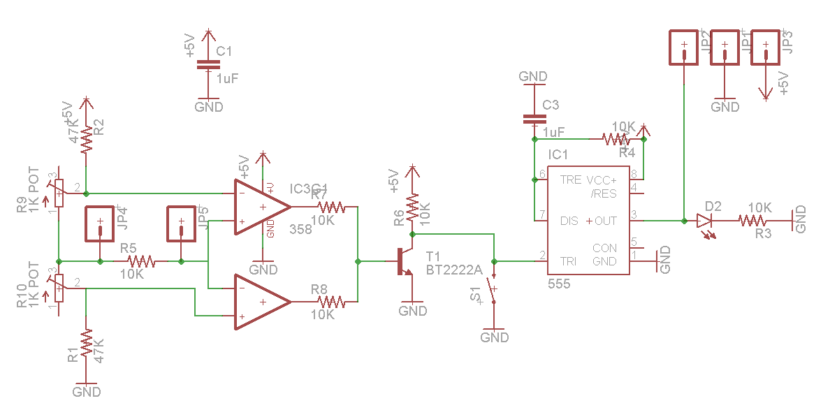
I have developed a touch probe for use with CNC machines that costs < £20 to build
To make the experience fit your profile, pick a username and tell us what interests you.
We found and based on your interests.
The piezo will itself generate a small voltage spike when it is flexed. This means that the method of detection can be as simple as triggering when the returned voltage goes away from ground (assuming one side of the piezo is grounded)
This has the drawback in that it requires a dual voltage op-amp setup so that both positive and negative voltages can be properly detected. Instead I have chosen to bias one lead of the piezo at 2.5V (or so). This means that any deviation from 2.5V will trigger the circuit.
Anyway, the above design is the smallest design I could manage while still including the test switch and the LED indicator. The biasing of the piezo is achieved by the two fixed and the two variable resistors shown on the left of the schematic. The two fixed resistors basically fix the max window range to ~2.45 - ~2.55V. The variable resistors allow for trigger level adjustment to a sensitivity that is better than my multimeter can measure.
To the right of the resistors are two jumpers with a resistor between. This resistor (R5) helps the piezo voltage settle in a short amount of time so as to avoid double triggering. The two op-amps are simply used in comparator mode, one triggering if the piezo voltage is less than the lower bound and the other triggering if the piezo voltage is higher than the upper bound.
The output of the op amps is fed, via current limiting resistors, to the transistor. This acts as an inverter and ensures predictable behaviour because of the pull-up resistor (R6). The switch is also able to trigger the output to help test the probing software and to avoid machine crashes.
The 555 timer is configured as a re-triggerable pulse former. This design is all over google with explanations that are better than I would be able to manage here. The important thing is that the 555 gives a fixed length pulse out from a jittery input. The pulse length is set by the resistor and capacitor pair (R4 and C3). The values displayed give a roughly 10µS pulse length which is plenty for the interrupt on the arduino.
This circuit has shown itself to be very sensitive to vibration and touch events. It is highly sensitive to the extent that it is impossible to walk in a room with a piezo stuck (with tape) to the floor, without it triggering on each step.
I can provide eagle files if people are interested and I will answer question on the circuit if people have them.
I had the prototype boards made up by OSHPark which is an amazing service that I will definitely use again. They cost less that £3 for 3...
I was testing piezo electric speakers for use with a product at work. I have researched touch probe technologies in the past and was vaguely aware of how sensitive they are. As I had an oscilloscope to hand so I decided to see how sensitive they were and was amazingly surprised by how ridiculous even the cheapest of piezo speakers are. The fundamental physical principle of piezo electric crystals is that a voltage is generated whenever the crystal experiences shear forces. The reason that they can be used as speakers is that this can also work in reverse, such that an applied voltage will change the shape of the actuator which emits an audible sound wave.

This is a trace of the voltage measured at the piezo by my Rigol DS1054Z. This is a typical trace for a direct tap on the piezo but its difficult to make repeatable. Note the vertical scale of 2V per division which shows the piezo is capable of huge output voltage which bodes well for this project. The horizontal scale is 2ms per division which means the response is fast and very low power.
Its starting to look like we might be able to make this work. Now we need to move on to looking at electronic detection methods.
Create an account to leave a comment. Already have an account? Log In.
If you use proper comparators with open collector outputs (instead of forcing op amps to do the job) their inbuilt ~2mV offset and high open loop gain allow elimination of the 2 pots at the inputs. The output resistors need to be reconfigured as pullups (to the open collectors) and 2 isolating diodes added, 1 to each output after the pullups.
You can also eliminate the 555 by adding a 100n at the output transistor's collector to create a 1ms pulse extension. (Just put the LED in series with its pullup if you need a visual).
Saves the cost of 2 pots & a 555, adds 2 small signal diodes and a small cap.
Model it with LtSpice to see how sensitive it is over a huge range of inputs.
bye.
If you use open collector outputs you can connect them together without
diodes to one common pull-up resistor.
The stylus on eBay would be a great way of getting consistent styli at a good price. Not sure how good a ruby you can get for £20 though.
Gluing a nut to the piezo is a very reasonable thing to do. I keep wondering if there is a better design for the piezo housing that would give some calibration but I am not making much headway.
I am trying to avoid using an ADC on a micro as it takes a lot of overhead and is not very quick to respond. A comparator is much faster and generated a digital interrupt for the MCU which I think will be fast.
Missed ticks is something I am worried about. I want some form of compliance but that is at odds with the tight repeatability requirement. I did debate using the break circuit type but the piezo was just so readily available and very compact.
Thanks, I've sorted the link now.
how about glue a nut to a piezo element, http://www.ebay.com/itm/CMM-Stylus-CNC-Touch-Probe-1mm-Stainless-Steel-ruby-tip-M2-/131691007727 grab one of these, then you have interchangeable tip sizes, connect it up to an ADC and watch for the threshold change.
you could glue the probe directly to the piezo as well since piezo elements are cheap.
might be a cheaper source of ruby tipped probes somewhere.
the only thing i see as a possible downside for them is if the initial pulse gets missed, with the break circuit types they're effectively latched, same thing if it is used as an edge finder sometimes i leave it on the edge checking to see if its lined up. still mulling it.
also img link in post is busted.
Become a member to follow this project and never miss any updates
Great idea! Did you made any progress on this project recently?