 andreas.betz
In the last log I mentioned the driver circuit for the voice coil. Here's a little bit more info on that particular piece of our setup:
Essentially this is just an adjustable constant current source, which displaces the lens within its magnetic harness. Andrew has a nice intro to the inner workings of the voice coil on his project. He sourced the current simply via PWM+resistor. Now, we're going a step further and have built a voice coil driver based on a linearised bipolar transistor.
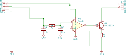
The idea is still the same as the PWM+resistor (meaning that the current is set by a "resistor" and its voltage drop), but now the bipolar transistor (PN2222A) acts as "variable resistor" here and its "opacity" is controlled by the set voltage on the base. This would already suffice actually for a constant current source.
However, the current through the PN2222A isn't linear with base voltage. To achieve a linear setpoint control, we've added an op-amp which provides negative feedback.
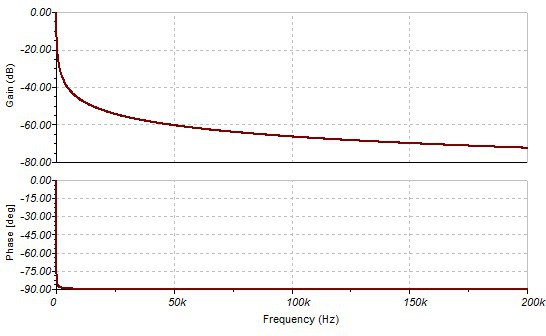
Finally, in order to increase stability, the setpoint voltage is filtered with a CRC pi-filter before going into the op-amp. The values used in the little breadboard version from the last post are actually 10uF-330Ohm-10uF. Plugging this into TINA-TI we can see that it should really remove all finite frequency components and leave us with a clean DC signal on the setpoint.
Discussions
Become a Hackaday.io Member
Create an account to leave a comment. Already have an account? Log In.