 agp.cooper
The Best One Transistor MW Radio Ever
Its a bold statement! Can you do better!
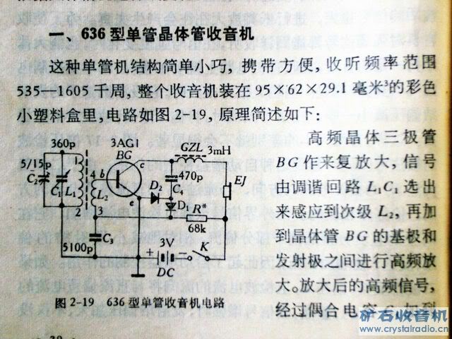
It's the 636 One Transistor Reflex:
And a video from the Internet:
Another example:
Here is my simulation of the 636:
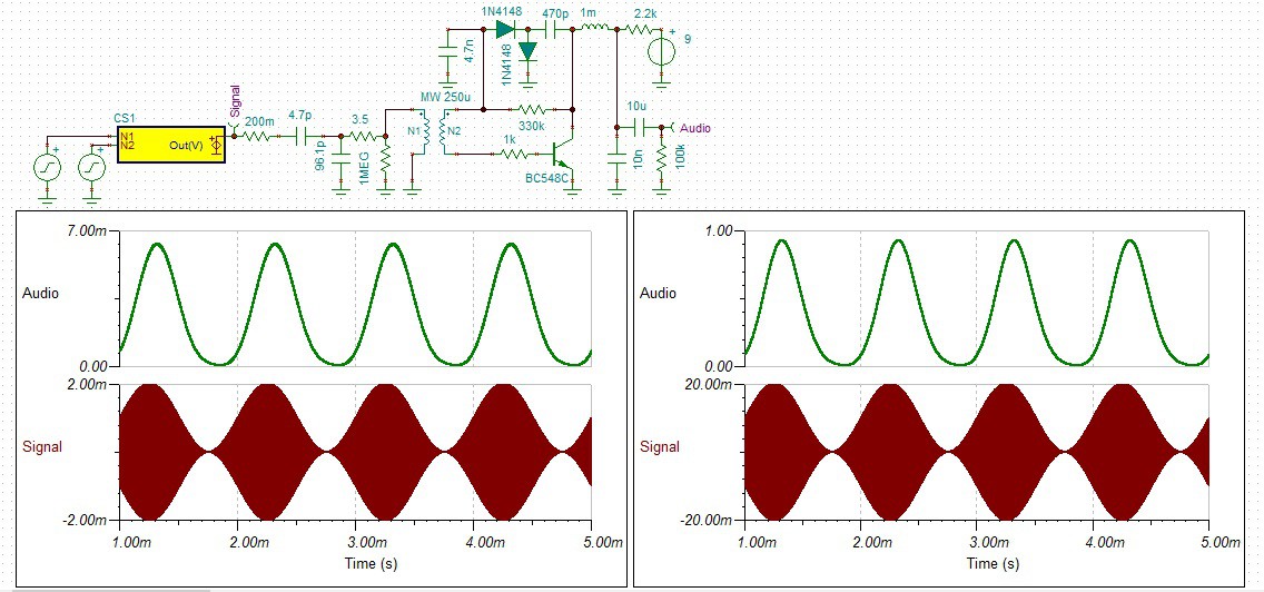
A number of changes were made:
- Modified for 9v and crystal ear-piece output.
- Added a 1k base resistor to stop "Colpitts oscillation".
The schematic consists of:
- On the far left, a the signal generator (before the the signal probe).
- Then the short wire antenna model.
- Then the tuning coil and tap at 10%.
- Then the 636 circuit.
Analysis:
- The left analysis is of a 1 mv 1 Mhz signal modulated by a 1 Khz audio signal.
- The audio shows a square law distorted audio output of 6 mv (a gain of x3).
- The right analysis is of a 10 mv 1 Mhz signal modulated by a 1 Khz audio signal.
- The audio shows a square law distorted audio output of 900 mv (a gain of 45).
Replacing the 1 mH inductor with a 1k resistor, reduced the gain by a factor of 3:
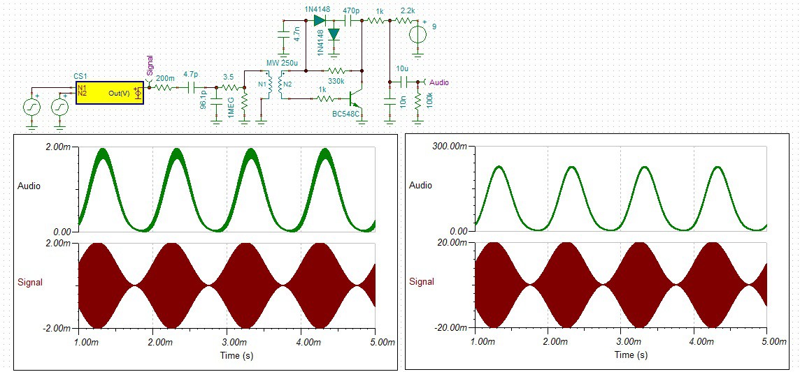
Increasing the tuning coil tap to 20% (from 10%) kills the tuning coil Q.
Over to you!
Discussions
Become a Hackaday.io Member
Create an account to leave a comment. Already have an account? Log In.
lovely
Are you sure? yes | no
The circuit is reflex so it has plenty of feedback (one pass RF and one pass audio). It has a square law response. Sensitivity is limited to a few mV from memory. But I don't use an antenna.
I have to include a base resistor in order to tame (unwanted oscilation) in my version. So their is some RF feedback as well.
In my version I use a spider coil, I tried a printed circuit coil but not as good (low Q).
I have tried Ge but SI works just as well, so why waste a Ge diode.
AlanX
Are you sure? yes | no
Can't you do a bit better adding a bit of positive feedback from transistor collector to primary winding of (presumably) ferrite rod inductor? That should improve both sensitivity and selectivity.
Are you sure? yes | no
I have to wonder if these get coupled a little through the inductors, depending on your layout, so sometimes the "circuit" works better than others. Other times, the phase is wrong, and it's worse.
Are you sure? yes | no
Did you try Ge (or Shottky) diodes in there? They might mess up the biasing with the circuit as it stands because of their lower forward drop, but maybe the audio could be coupled from the diode doubler back to the base with a large cap. They should increase the sensitivity, I would guess.
Are you sure? yes | no
The diodes are forward biased here, shifted into region of lower dynamic resistance, that may explain the little differences that @agp.cooper experienced.
I remember building "crystal set" with Ge diode and its battery operated version with no transistors, but the battery was used as current source to forward bias the diode. Sensitivity increased, though once the battery was in circuit, crystal set lost its spirit; using transistor was better then.
And small matchbox sized receiver for fixed frequency, with two transistors and diode, all of them were silicon parts. I dug out the schematics for you, see here https://snag.gy/6vcW5x.jpg It was powered by single 1,5V AA cell, with small ferrite rod antenna (~1cm diameter, 4cm length) it picked transmitter located 50km away just fine, with plenty of loudness made by 50Ohm telephone speaker. I was 13 years old then, listening morning program of Slovak AM broadcasting during school lectures. The program was unbelievably boring, but I listened to it anyway, to keep my status of ultimate coolness, with DIY radio.
Are you sure? yes | no
I have never made a reflex, but I've wanted to for a while. That 636 circuit looks a little like an NPN version of this reflex-regen design by Clive Sinclair:
http://theradioboard.com/rb/viewtopic.php?t=7572
Are you sure? yes | no
Looks to be the same as Clive's but the description of operation does not match my simulations. Gain is a square law, not AGC?
AlanX
Are you sure? yes | no