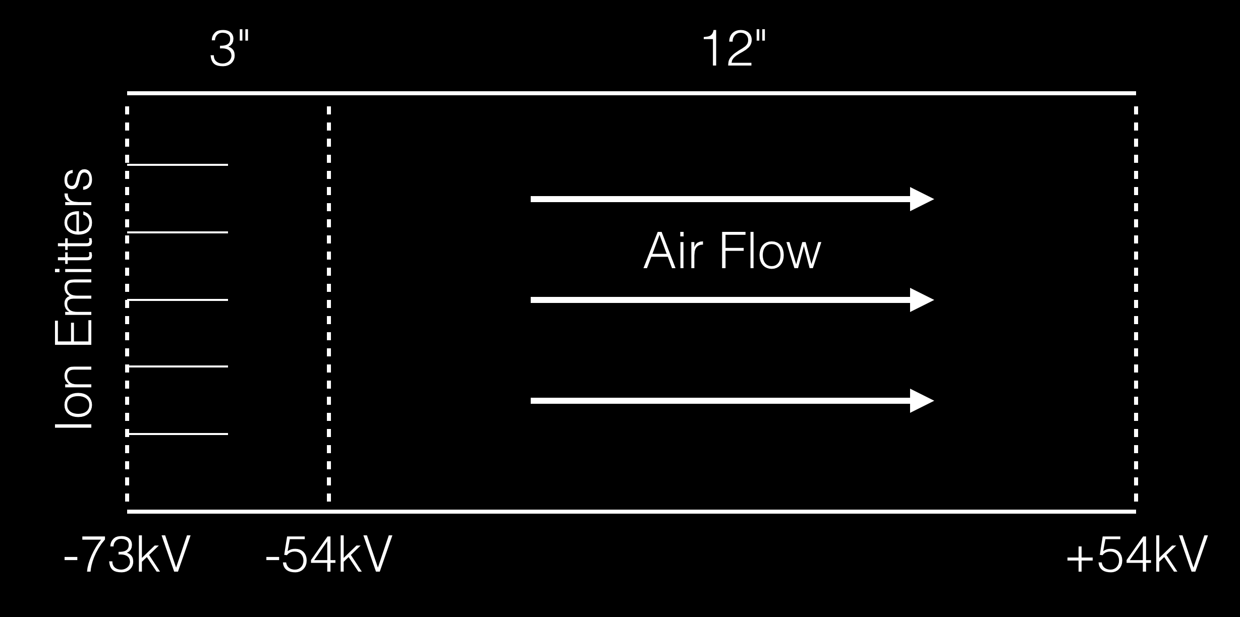
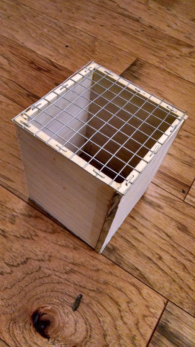
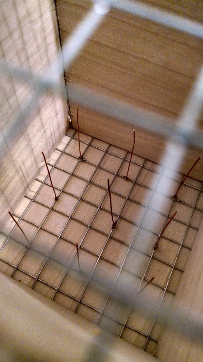
The initial thruster design is fairly simple and is divided into two sections. The first section is responsible for producing the negative ions used by the second section. The second section houses screens that produce a static voltage gradient. The static voltage gradient exerts a constant force on the negative ions which pass between the screens and the counter force from accelerating the negative ions produces a forward thrust. Separating the ion production from the acceleration chamber minimizes the chance of producing a conducting channel and triggering an arc-over event.
To minimize fringe effects and promote a uniform voltage gradient, the sides of the chambers will house the voltage multipliers. The multipliers have been designed to present a uniform voltage gradient along their length when energized. With a 12 inch separation and a 108 kV differential voltage, the field strength in the acceleration chamber will be 354 kV/m. This yields 354 kN of force for every coulomb of ions present within the chamber. Assuming a current of 10 mA and air flow of 1 foot per second, there would be 10 mC of ions present within chamber which would produce a force of 3.54 kN or 79 lbs. While impressive, this number does not reflect reality since the resultant force would accelerate the air column which, in turn, would would increase the air flow velocity and reduce the ion density in the chamber. The purpose of this project is to observe the equilibrium state under various ambient air flow velocities and observe the amount of thrust produced and the power consumed.
While the diagram shows the ion emitters as having a potential voltage of -73 kV, this is merely the maximum voltage. The actual system provides current limiting and will supply whatever voltage produces the desired current flow.
Please see #Ionic Thruster Power Supply for details about the voltage source used in this project.



 mircemk
 Azri Jamil

 JP Alfonso
Robert,
If you will tell me what you hope to accomplish (payload, speed, acceleration) and how you intend to measure your results, I might be a bit more specific. I don't have a very good idea of what you have done and intend to do.
Does your device actually move air? How much? Do you have a way to measure pressures and forces? Velocities, vorticity, temperatures, densities, composition?
Here is an interesting approach where they use lasers to activate the air, and then electric fields to provide the energy https://arxiv.org/ftp/arxiv/papers/1801/1801.06778.pdf
I think that ionizing the air, molecule by molecule, is expensive. Do the numbers. But, if you can hit molecular groups and transfer momentum, going in the right directions, you can be more efficient.
I guess your goal is to move craft in air, not move air itself? Have you done the basic calculation for holding flight? If you keep the craft perfectly stable, it requires less and less power. When you let things drift the cost goes up. Could you try to get a self-levitating engine, then try to optimize the measurement systems and controls to reduce the power requirements to the minimum? Start with dx = (1/2) g * t^2 and try to minimize the uncontrolled time of falling. That gives a small dt and a higher restoring frequency. If you use MHz acoustics there might be a sweet spot that gives decent power requirements for weight, and low cost control systems
Richard