Diagram

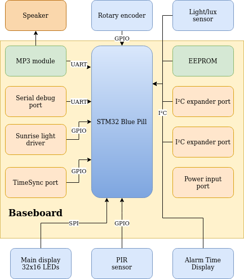
The diagram above gives an overview of the baseboard. The yellow background represents the baseboard and the functionality present onto it. The other modules (speaker, rotary encoder, sensors, displays) are external modules.
- Microcontroller platform selection
- Audio module
- User Input Control
- Ambient light sensing
- Movement detection sensor
- Main display
- Alarm time display
Old data:
Rev.0: IO Panel : LCDs, switches, IO expansion, LED array, light sensor all integrated on one PCB
Verifying interfacing to peripherals
- ☑ MP3 module
- ☑ Serial debug port
- ☑ Main display 32x16 LEDs
- ☑ 2x I²C expander port : Unfortunately, both connectors should have been 14pins FFC instead of 10pins FFC now. I solved it by cutting off three tracks of the FFC-connector. It would have been a cleaner workaround to replace the FFC-connectors on the I²C-expansion boards by 10pin types. But then I would also have to buy 10pin FFC-cables.
- ☑ EEPROM
- ☑ Rotary encoder
- ☑ Time sync port
- ☑ PIR sensor
- ☑ Alarm time display
- ☑ Light sensor
- ☑ Sunrise simulation
 Christoph Tack
Discussions
Become a Hackaday.io Member
Create an account to leave a comment. Already have an account? Log In.