Background
A gradually brighter light can mimic the sun rise. It will allow for gentle wake-up in the morning.
Experience with the Philips HF3463 showed me that you shouldn't count on it to get up on time. I sometimes find myself waking up by the alarm sound and facing the alarm clock in full brightness. When you're sleeping on your side and the light is behind you, it won't wake you either.
LED driver modules
The plan is to power the clock from a 5V USB power adapter. The LEDs require about 12V/500mA. So we need a boosting LED module, not a buck module.
If we decide to make the module ourselves, we need to select an IC:
- easy to solder : SOT23 is ok, QFN isn't
- over voltage protection (when LED is not connected or broken). Proper solutions directly sense the output voltage using an extra pin. This brings the minimum number of pins for the IC to 6 : gnd, vin, vout, sw, fb, en.
- VIN min < 5V
- VIN max > 5V
- VOUT min > 12V
- IOUT > 1A (we need 500mA). Don't confuse this with the switch current. The input current of a boost converter is essentially the inductor current. When the boost converter switch is conducting, the input current is equal to the switch current. If we need 6W at the output, we need at least 8W at the input. The switch current should be at least 2A to be safe.
- low power. Remark that the output LEDs continue to draw current when the LED module is in shutdown. External circuitry is needed to fully shut down the LED module.
- dimming capability (analog & digital dimming are explained in the MP3202 datasheet)
Digikey selection (for 1A switch current): RT4533GJ6 and MP3202 (pin compatible), TP61165 (not pin compatible)
In the hindsight, the LM3410 would have been a better option, because it allows for larger drive currents.
Revision 1.0
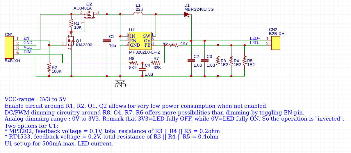
Details about this circuit can be found on EasyEDA.

The circuitry above has some issues:
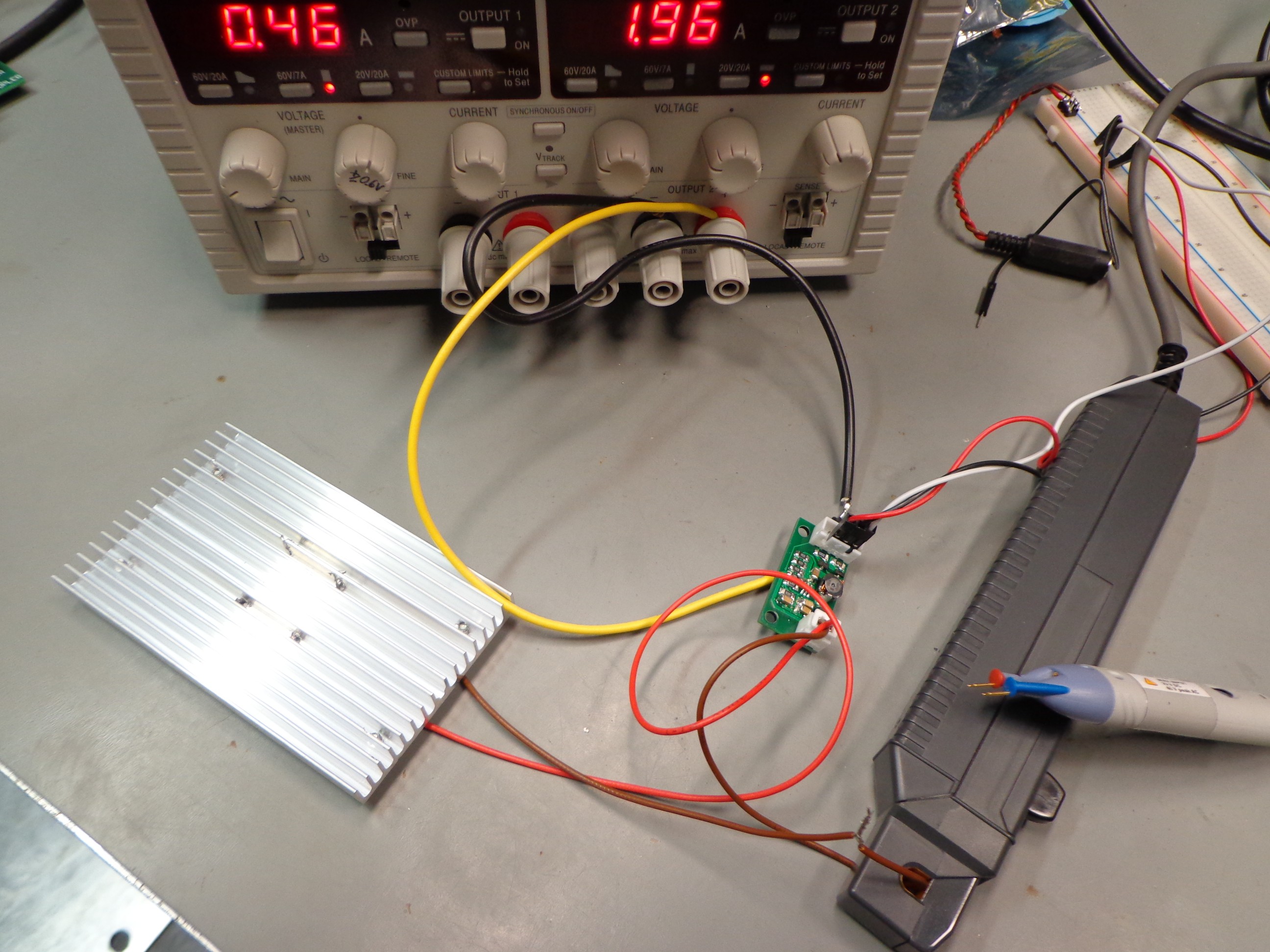
- Thick wires must be used for VCC & GND because they have to carry up 1.1A. These wires will probably too thick to fit in the JST-XH. For debug, I soldered thicker wires on bottom side.
- The current is set for 500mA, but only about 400mA is being drawn. The feedback voltage never reached 200mV. The 0.4ohm sense resistor combination had to be replaced by a 0.5ohm (2x 1ohm) resistor combination.
- Value of the resistors for analog dimming are too big. As the PCB is quite small, they pick up some noise. Making them a factor of 10 smaller improves it a lot.
The RT4533 announces itself as boost converter for 10W LEDs 10 WLEDs. It's important where you put the space. Richtek means you can drive 10 white LEDs. It's easy to misread it as : "RT4533 can drive 10W LEDs".
It may well be possible to drive LEDs, but not at 10W. Let me explain:
- The maximum input voltage for the RT4533 is 5.5V
- The maximum switch current is 1.2A. For a boost regulator, this is also the maximum current through the inductor. The current through the inductor is essentially the input current to the circuit.
- So maximum input power is 5.5 * 1.2 = 6.6W
- Let's be optimistic and assume the output power is 80% of the input power : 5.3W, which is far from the advertized 10W.

Measurement results
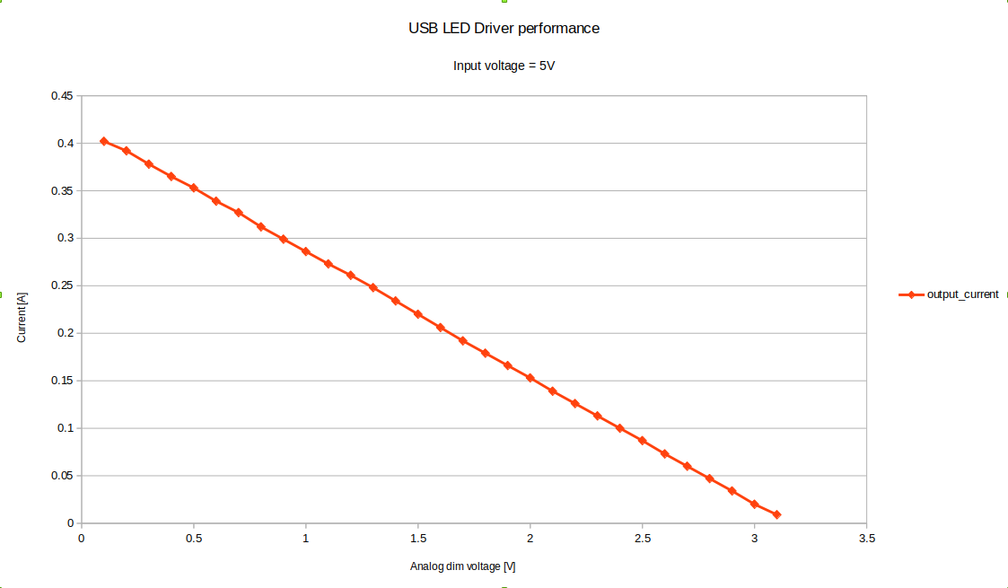
The output current drops linearly with the control voltage, as expected.

The module already saw a second use as a replacement driver for lighting the christmas tree. The original driver was specified for 32V/100mA. Setting the two sense resistors to 3.9ohm and you're done. Power draw on the 5V power supply was about 800mA.
Dimming the light using PWM
Earlier experiments with dimming LEDs showed me that 8bits is not enough to generate smooth transitions. The step from 1/256 duty cycle to 2/256 is very noticeable. Once you're at duty cycle 200/256, increasing the duty cycle doesn't make much difference.
A simple way to increase the PWM resolution is to use two PWM channels, a dual RC-filter and an opamp. Hackaday already published an article about the subject.
Needed output power
A Philips HF3463 sunrise clock uses a Philps 100W 1200lm Softone lamp. Replacing the bulb with a 60W 700lm still gives enough light. So our light should also be able to output about 700lm.
Selection of the lighting source
- Lumileds Luxeon 3535L & Lumileds Luxeon 3535L HE Plus
- Devices available at Mouser & Digikey:
- LEDs cost about €0.42/pce
- >180lm/W
- 300mA max, lowest cost per lumen. Other 180lm/W devices cost about the same but don't allow such high currents.
- If driven at 200mA, then 7 LEDs would yield about 800lm.
- "Could" be soldered to custom Al substrate PCB.
- AllPCB : 120x20mm or 100x30mm is $17 / 5pcs
- How hard is it to solder LEDs on a metal substrate?
Bridgelux BXEB-L0280Z-50E1000-C-B3- 280x24mm, which is too long for the alarm clock
- 180lm/W
- 19.5V, 350mA, 1230lm
- Digikey €3.12/pce (not available)
- COB LEDs
- DopDea DPD-36120-0428
- Rectangular 120x36mm, 112 LEDs
- 10W, 1100lm according to AliExpress
- Unrealistic specs on DopDea website
- AliExpress ZHONG ZHOU EVER LIGHT Store: $2.00/pce
- Dimensions can be found here
- DopDea DPD-9450-0414, ZF-9450-0414
- DopDea DPD-36120-0428
5050 LED panel- Available on AliExpress
- Designed to replace incandescent light bulbs for car interior lighting.
- The LEDs seem to be Seoul Semiconductor STW8T16C-Q0S0-HA.
- The version with 24 LEDs should be bright enough.
- Disappointing output : 80Lux at 1m, I=500mA, U=17V
GU5.3 Base fitting for MR16 lamps- 12V lamps
- typically 500lm, which is rather limited
- heatsink is part of the lamp
- AliExpress has many on offer, very cheap
- In a local store it was hard to find LED lights with a GU5.3 base. GU10 (230V) is the most common type of lamp. The best GU5.3 base LED lamp suitable for this application:
- Philips
- 8W
- 12V AC/DC
- €11.95 (no kidding)
- 630lm
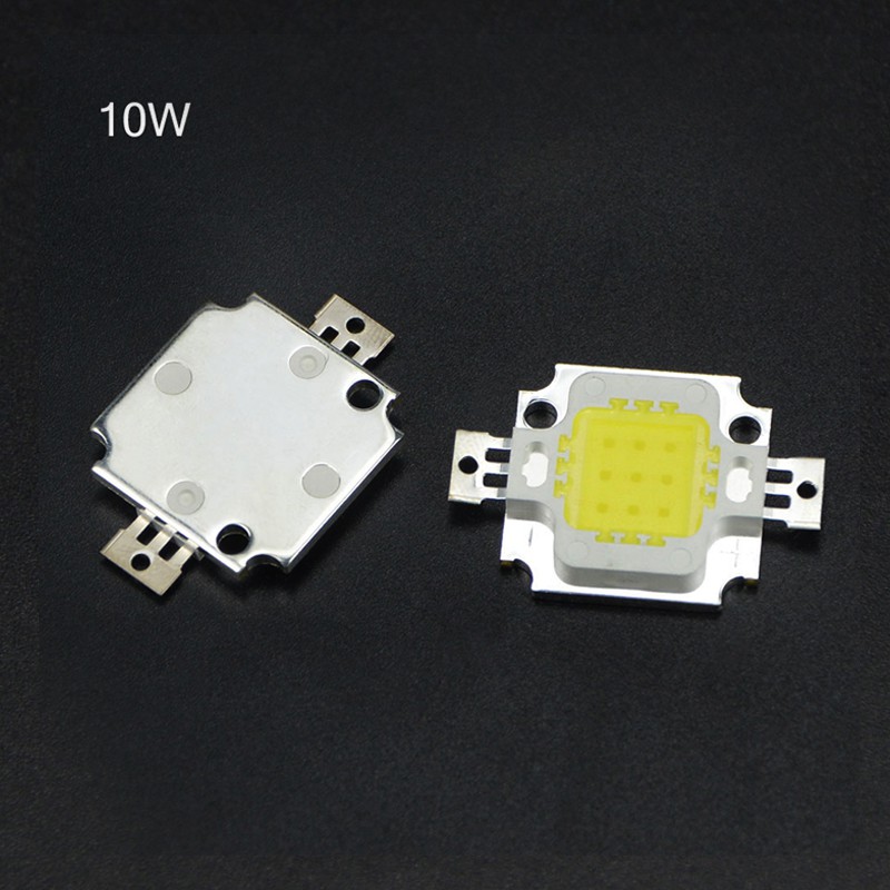
Wayjun Epistar 10W![]()
- available on AliExpress from many vendors
- commonly used in floodlights
- cheap : $0.29/pce (cheap version 900mA), $0.94 (real version 300mA)
- A sample of each has been ordered. I received both but don't know which is which. I asked the seller and they replied that the "heavier" one is the real one. The "real" one is indeed about 4g heavier.
- They were both announced as warm white, but the "real" one is cold white.
- The warm white one has a terrible thermal efficiency. Without heat sink, the current needs to be lower than 100mA, or the LED will run too hot (>70°).
- The light output of the warm white one is disappointing too.
- The cold white LED performs a little better, but it's still disappointing. Too much of the power is lost in heat. These LEDs can't be used.
- AliExpress "specs"
- limited efficiency : 58lm/W (worst case for the cheap version)
- 11V, 1050mA, 675lm
- heat sink needed
Backlight panel- expensive: 100x100mm = €3.84
- limited light output
220V light with dimmer- requires 220V, which could be dangerous
- consumes a lot of power because of the inefficient lamps
NeoPixel ring- No need for color changing the light
Controlling the room light- Standard light with controllable dimmer: You need a dimmer that can be remotely controlled
- Philips Hue White Wireless bulbs : if you have a lot of money to spend
LED string- Inefficient because of the many series resistors in the string
Light source cooling
The above mentioned LED COB sources require that the aluminum substrate is not hotter than 70°C. If we want to maximize light output, we'll have to add a heat sink to get rid of the excessive heat.
There's no reliable info about the thermal resistance of the LEDs. Some tests will need to be done:
- Attach thermo couple to the LED strip
- Measure room temperature T1
- Leave LED panel hanging in free air. Don't lie it flat on a table or other surface.
- Attach current source to the LED and regulate current (I) so that steady state temperature of Al-substrate of LED is 70°C (T2)
- Measure voltage over LED (U)
- Calculate thermal resistance of LED panel = (70-T1)/ (U * I)
- Attach heat sink to LED panel.
- Repeat step 1-5.
A 100x60x10mm : €1.55/pce heat sink will be used.
This is not the cheapest heat sink around. Care should be taken to the thermal resistance of the heat sink. The LEDs can work up to 85°C. Any hotter and their lifetime will decrease rapidly. At a room temperature of max. 40°C, this allows for an extra 45°C temperature rise due to LED heating. The total resistance of the thermal path should be smaller than 45°C / 10W = 4.5°C/W. The thermal resistance of the LED is already 1.4°C/W. This leaves about 3.1°C/W for the heat sink.
AliExpress vendors don't publish the thermal resistances of their heat sinks. We'll have to measure thermal resistance by ourselves.
Another way is to go with some simple rule of my old colleague : "If your heat sink is too hot to touch, then it's too small".
 Christoph Tack
Discussions
Become a Hackaday.io Member
Create an account to leave a comment. Already have an account? Log In.