Close
0%
0%

remote controlled boat

it's a boat, and it's remote controlled.

Similar projects worth following
this is a project documenting my third model boat. it was built concurrently with my computer. I started it in march of last year and finished in late November of last year. It is not an exact replica of any real life boat, but is loosely patterned after turn of the century muskoka steam boats.

the hull is about 20 inches long, 6.5 inches wide, and 5.5 deep. it is constructed out of quarter inch birch plywood, pine strips, and some cedar, oak, and balsa. it is currently setup to run with a 2 channel receiver, providing forward, reverse and steering. the drive motor is a simple DC motor I salvaged out of a discarded printer. the boat runs off a 12v SLA battery.

this is a completed project, so I'll be publishing the 'project logs' all at once. I'll be covering a different piece of the project in each log. in order:

  • the hull
    • everything from the first drawings to the final sealing of the hull
  • electronics
    • battery to motor
  • drive system
    • propeller, rudder, and associated mechanics
  • decoration/misc
    • deck houses and finishing work

If you want help building a similar boat, or think that I need help building boats feel free to comment/message me. or just download the plans and claim you did it all your self, I really don't care.

  • details

    zaphod02/01/2016 at 21:29 0 comments

    I'll talk a little about the deck house and finishing work that went into the boat.

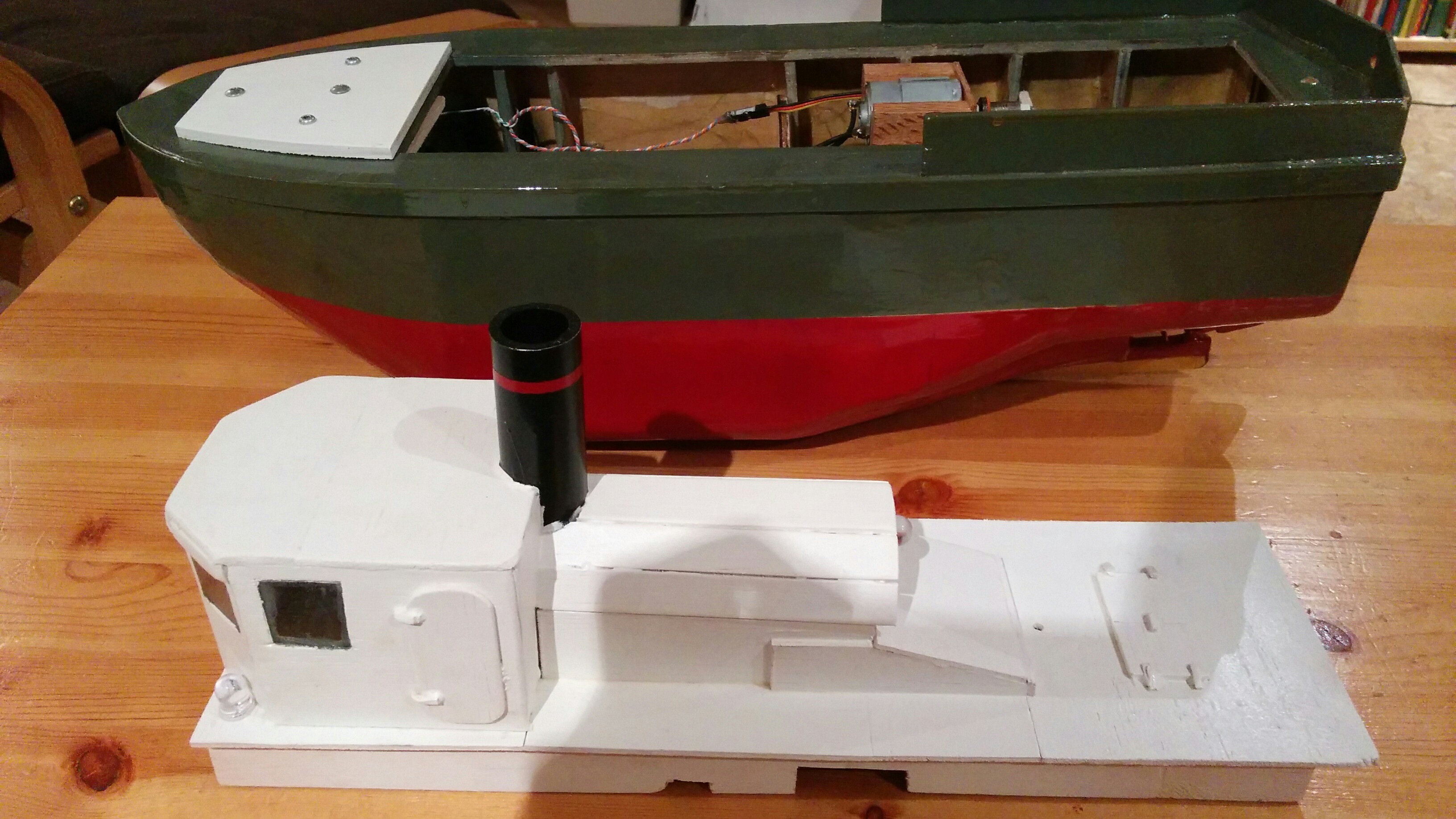
    the deck house is built on to the deck and lifts out of the hull like a lid:

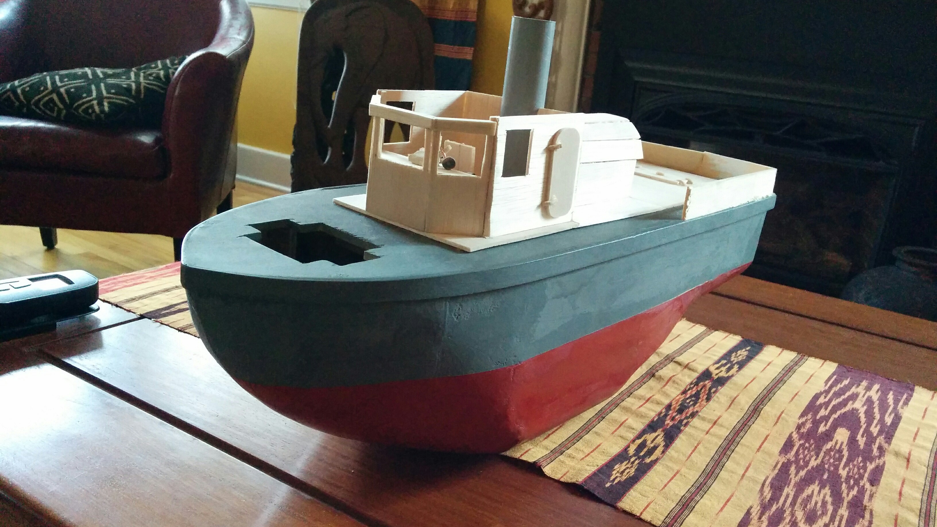
    construction was pretty simple, its just built out of sheets of balsa. the smoke stack is a piece of pvc pipe:

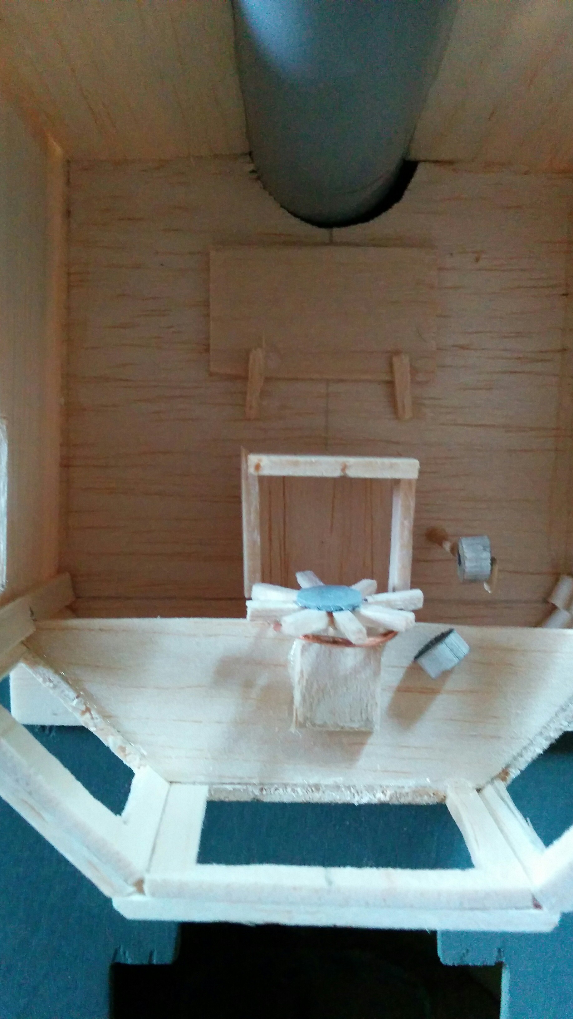
    I also added some detail inside the deck house:

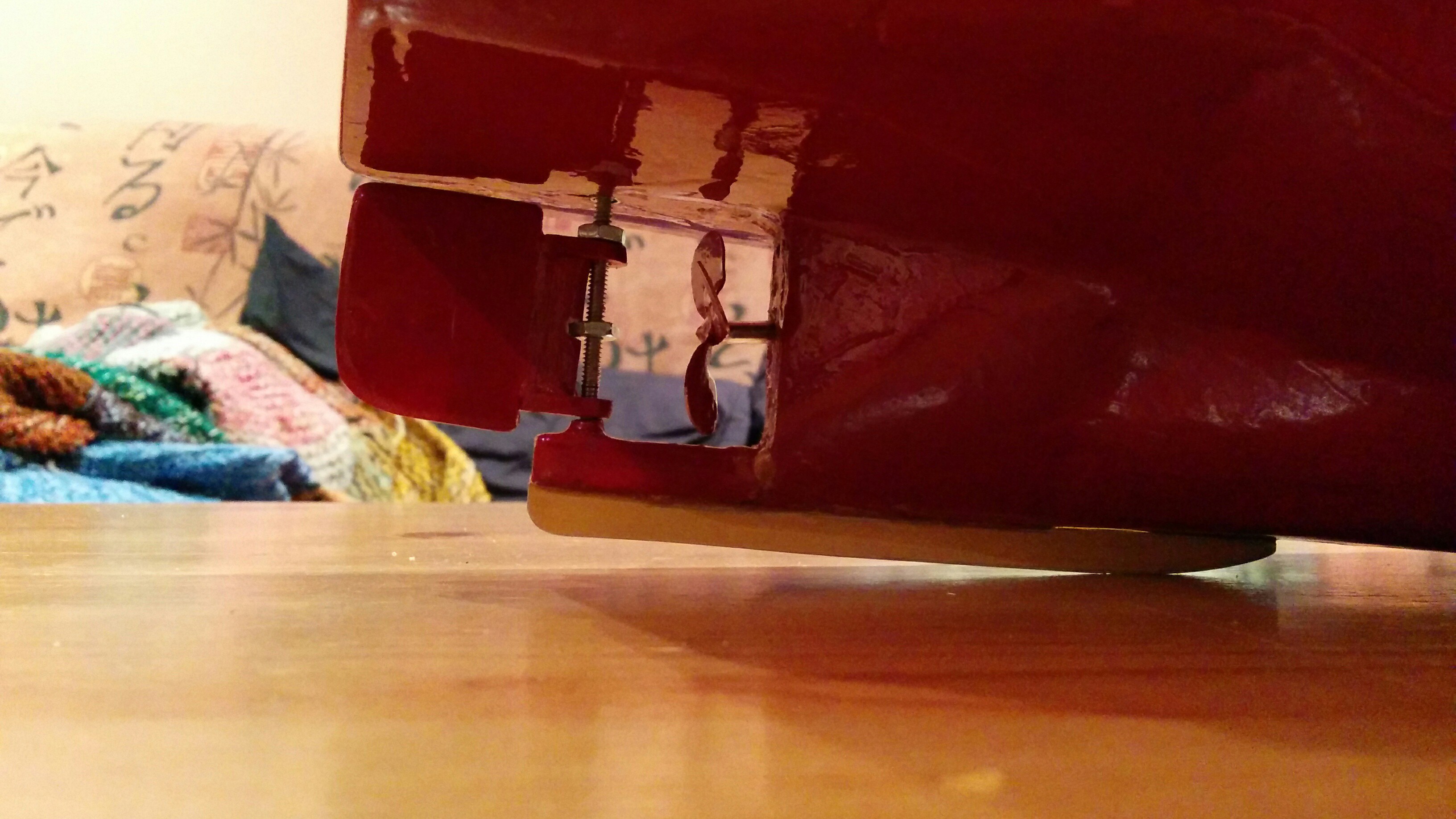
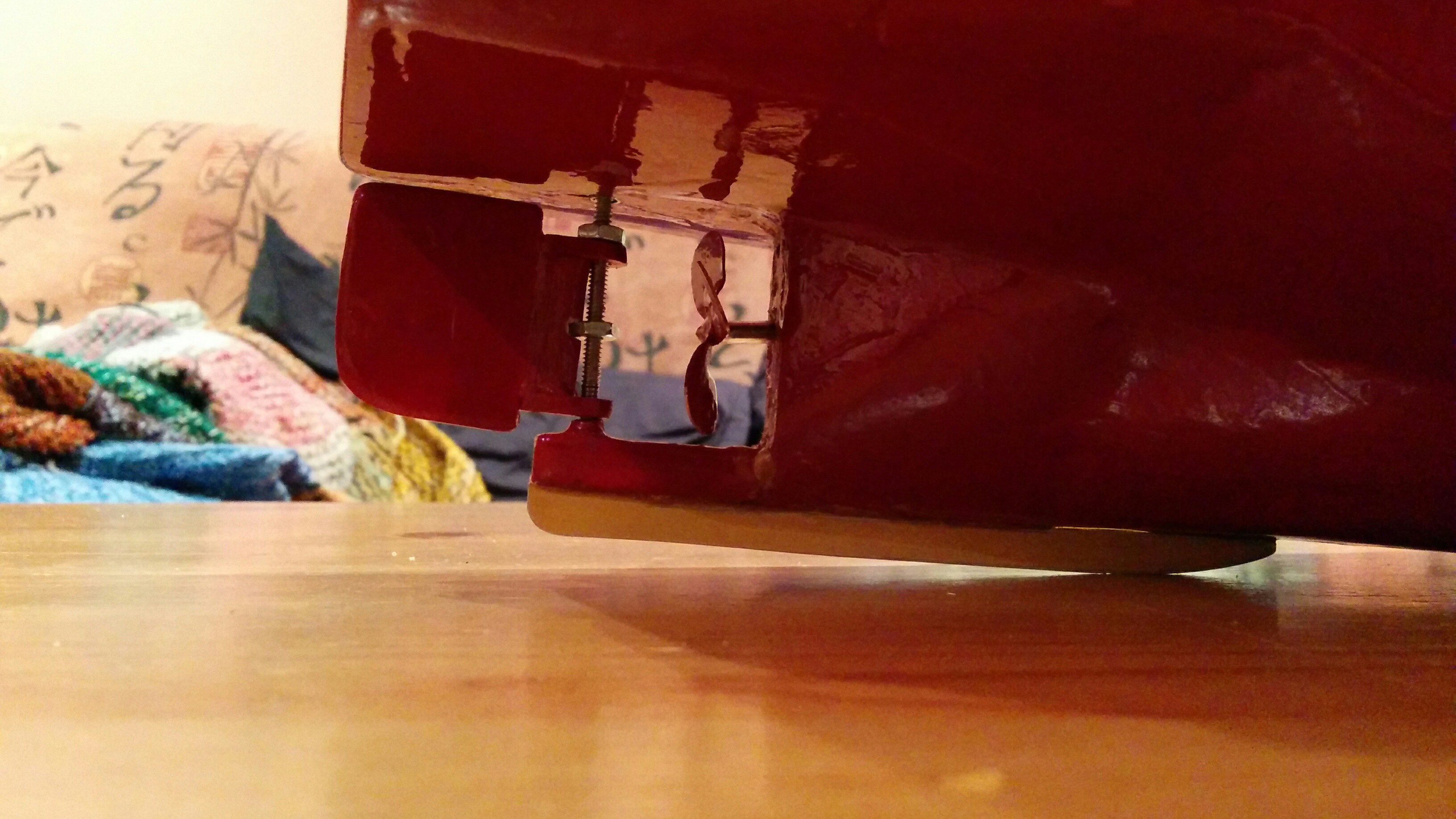
    I also mentioned I had some trouble with the skeg. I'll talk about that here. as you may have noticed in the drawings the skeg is a bit of a weak point, and sure enough it broke off during construction. to fix that I added the aluminum blade along the keel seen here:

  • drive system

    zaphod01/31/2016 at 21:43 0 comments

    this stuff:

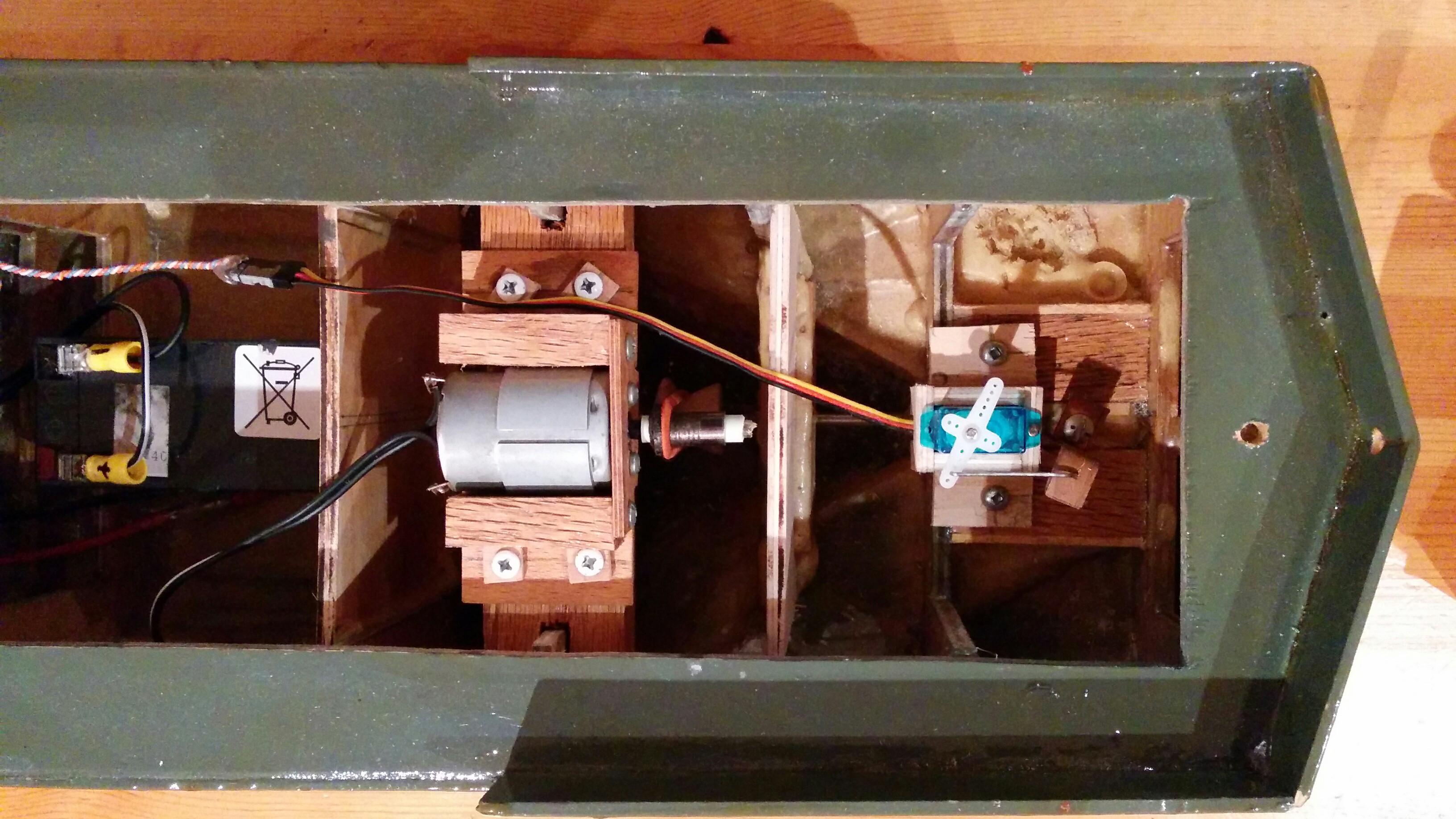
    here's the inside of the boat:

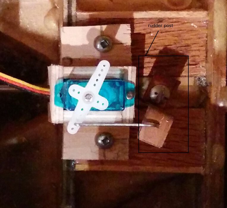
    basically the drive system has to do two things: propel the boat and steer it. I'll talk about steering first. the steering system is pretty simple, the servo is linked to the rudder post and the rudder is bolted to the rudder post. here's the linkage inside the boat:

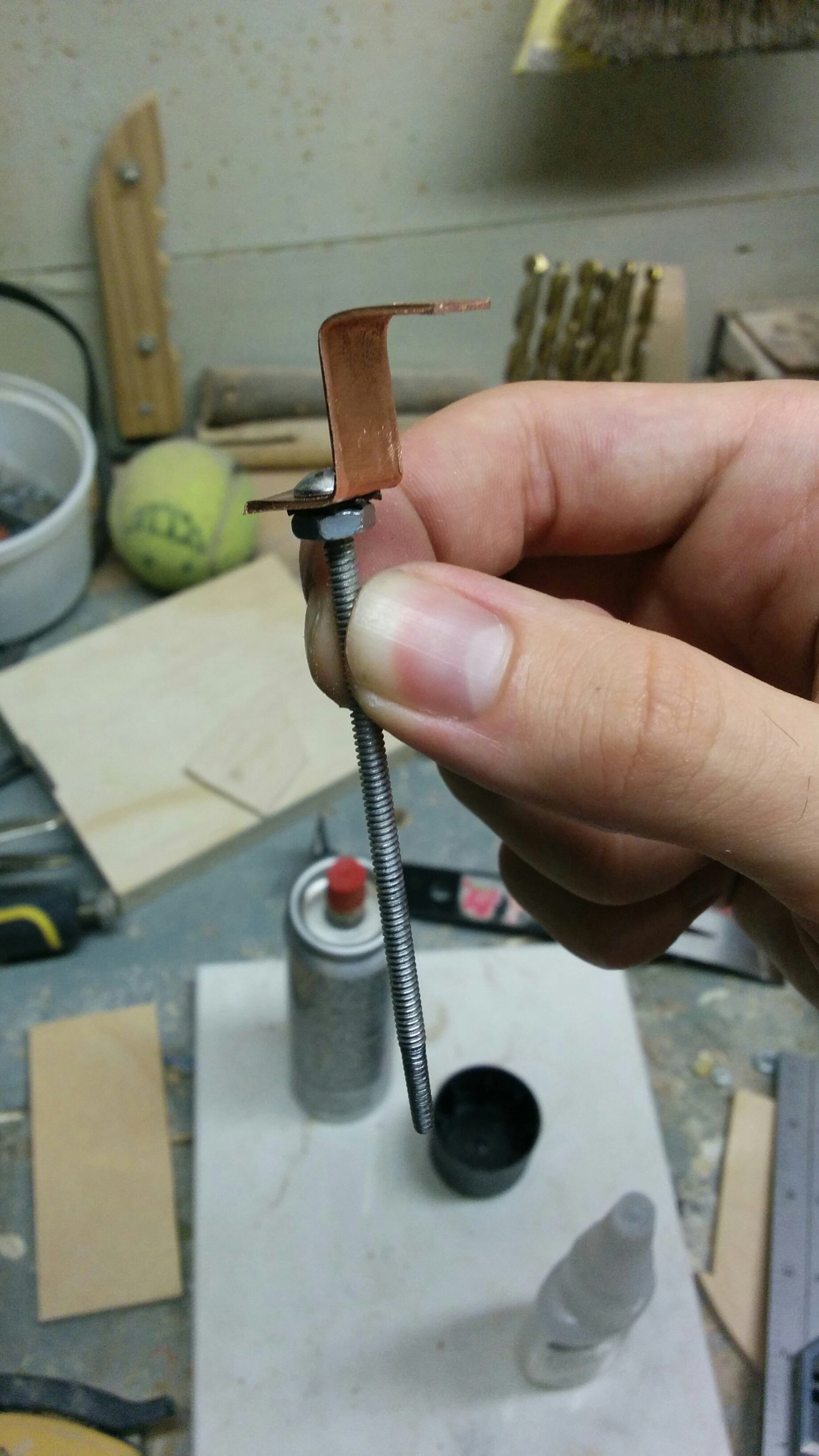
    and here's the rudder post on it's own:

    the rudder post is a bolt with the bottom 3/4'' of thread ground off so that it seats in the skeg. it also has a copper bracket attached just under the head, the bracket acts as a lever so that the servo can turn the rudder assembly (second picture). the rudder post needs to pierce the hull. in order to keep the hole small (and easily waterproofed with grease) I made a sleeve by drilling out the female half of a chicago screw and gluing it into the hole I made in the hull. to keep the rudder post aligned correctly I also made a cup in the skeg that the bottom of the rudder post sits in. the rudder is attached to the rudder post with a couple of small nuts.

    propulsion:

    the propulsion system was a little more difficult to build. in order to have spinning propeller there must be a hole drilled in the hull, naturally this lets water in, there are a few ways to deal with this:

    1. angle the stuffing tube: if the stuffing tube is angled enough its end can be brought above the waterline, this prevents water from getting into the hull. an angled stuffing tube is the simplest solution, but it comes with a few disadvantages. first: since the propeller is angled the thrust vector it produces is angled, meaning that some of the motor's output is wasted trying to lift the hull out of the water. second: as the boat pitches and rolls the waterline can briefly change, if it rises past the end of the stuffing tube the hull can flood.

    2. use a bilge pump: have a pump and a water detection circuit to bail out the hull. this method is often used on real boats, but isn't very applicable on model boats, as I found out. small reliable pumps that can provide enough suction to draw water out of the hull are fairly expensive and delicate. I had originally planed on using a bilge pump, the pump that I was using couldn't handle the strain and burned out.

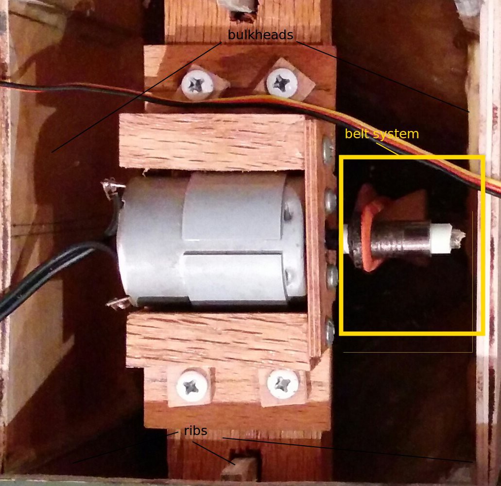
    3. wet compartments: include a structure within the boat that limits were the water can flow. this is the method that I ended up using. I added bulkheads at ribs H and F, and connected the motor to the propshaft via a belt. this way the motor is raised up out of the water and the bilge can flood to an extent.

    here's the motor mount and bulkheads:

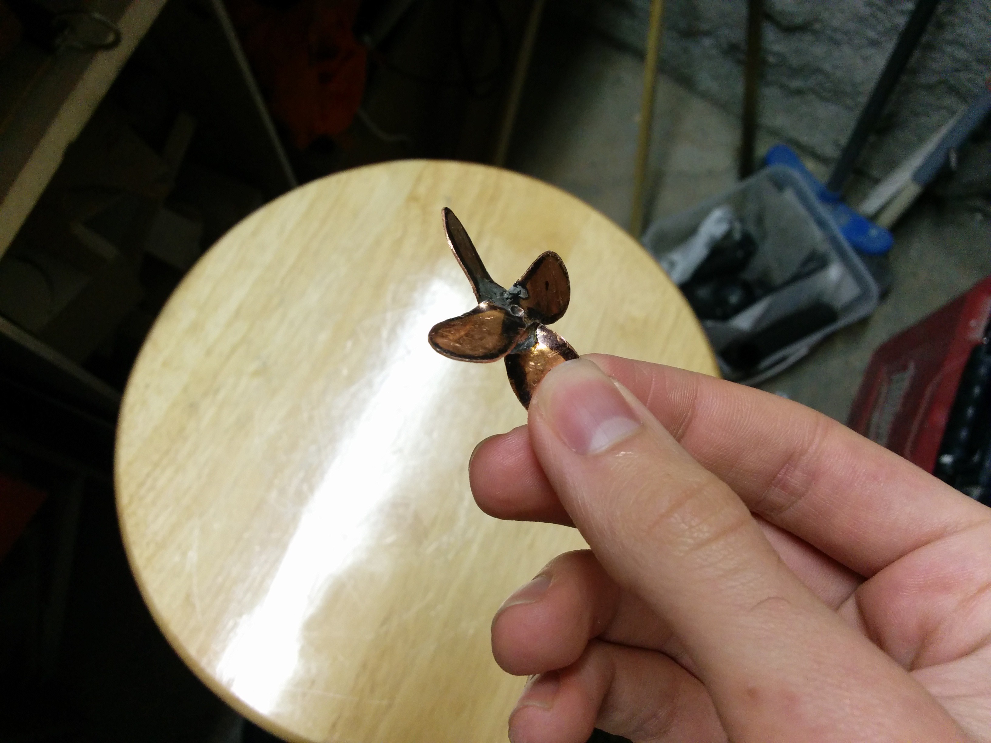
    the actual propeller for the boat was made from some copper pipe-clips. here it is before it was painted:


  • electronics

    zaphod01/29/2016 at 22:23 0 comments

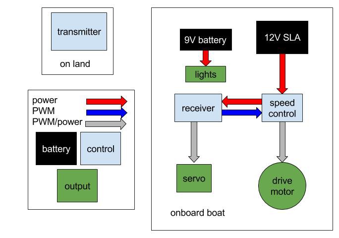
    the electronics on the boat are pretty simple. here's a block diagram:

    the electronics are fairly standard (and cheap) remote control electronics. as previously mentioned the transmitter receiver pair is a fairly simple 2-channel 2.4GHz setup with (supposedly) 2km of range. the servo that I am using is small enough that it can be driven directly by the receiver, so I don't need any thing more complicated to steer the boat. the servo is a simple 90 degree plastic gear servo as found in your junk box. I had originally designed my own speed control for the boat, but it ended up not working as well as I had hoped. additionally the first version of the boat's electronics had included a bilge pump but that was edited out of the design after a couple of fires. I'll be talking more about that in the next section. As of right now the speed control and receiver power are handled by a cheap ESC circuit that I found online (dx.com, don't have the exact link right now. I can dig it up if anyone's interested). the drive motor is a simple DC motor that I pulled out of a broken printer, it works shockingly well considering were it came from. the whole mess is powered by a 12V sealed lead acid 'alarm' battery. I went with an SLA for a few different reasons. firstly cost: they are dirt cheap compared to other remote control batteries. Secondly ease of use: depending on the specific chemistry of the battery rechargeables can be pretty picky about charging cycles, generally speaking lead acid batteries are not, also I already had a charger in my junk drawer. Thirdly weight: SLAs weigh a ton, which is not an advantage if you're trying to build a quadcopter but is great if you have to displace a few litres of water to get the correct draft.

    the boat also has some navigation lights, specifically the port, starboard, and aft lights, although no masthead light because I'm lazy. since I don't have enough channels to control the lights from my transmitter I just plug them in when I want them on and leave them unplugged when there are unneeded. the lights are just coloured LEDs running of a 9V.

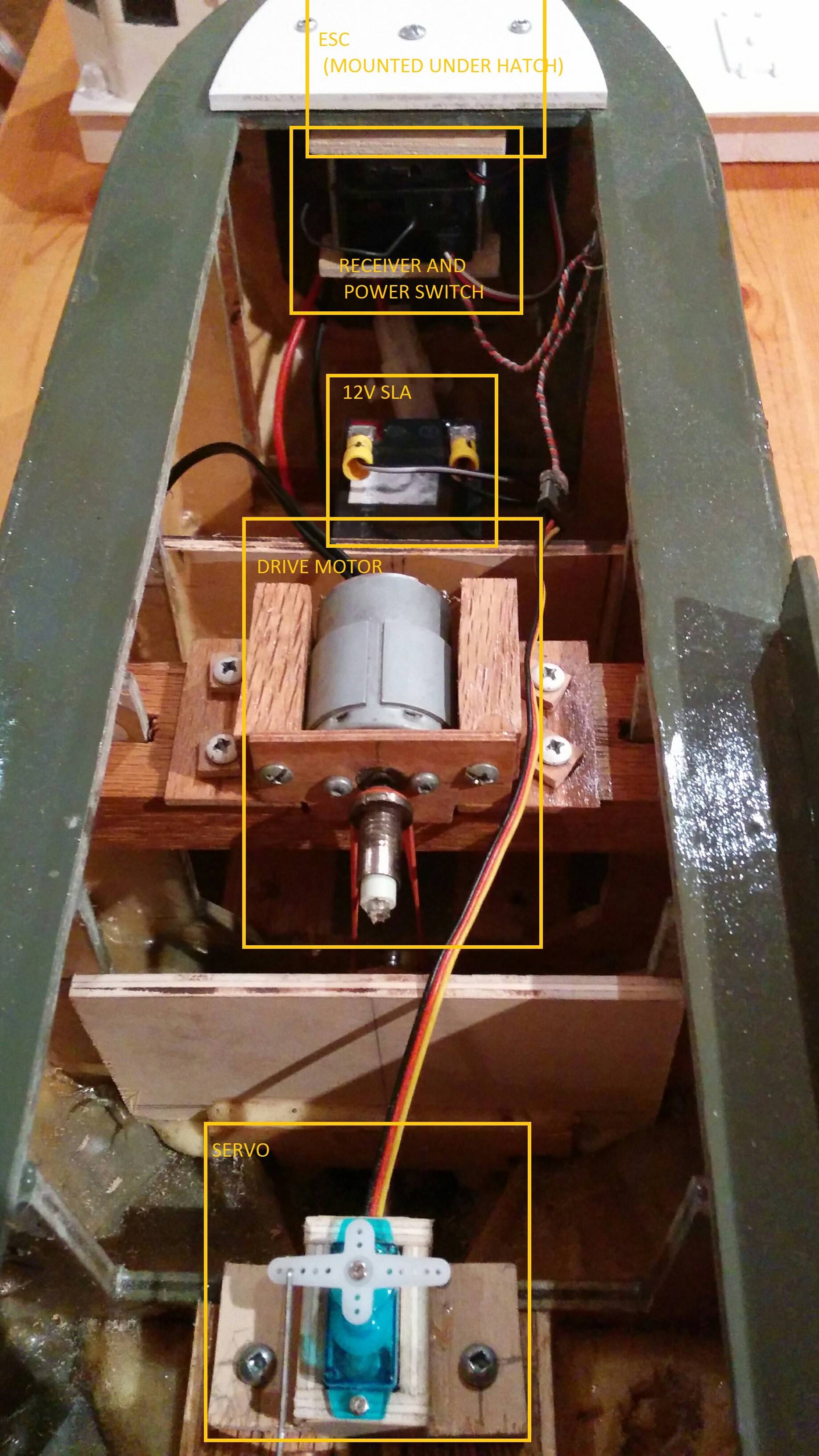
    main electronics:

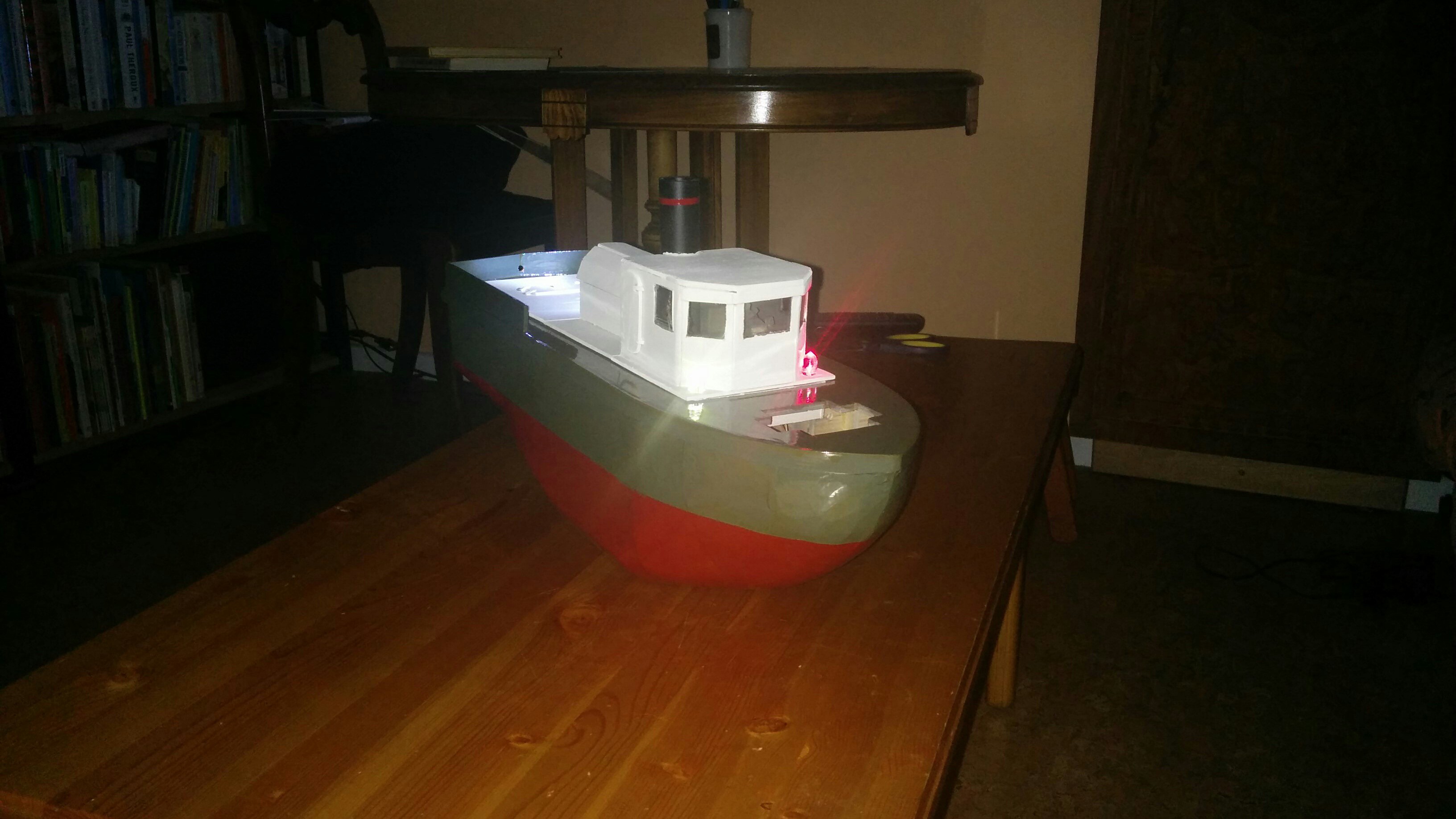
    this picture is taken from the aft looking forward. note the belt drive on the motor.

    and here it is with the lights on:

    no point in including pictures of the wiring behind the lights, its pretty much just a resitor soldered to an LED.

  • the hull

    zaphod01/29/2016 at 17:26 0 comments

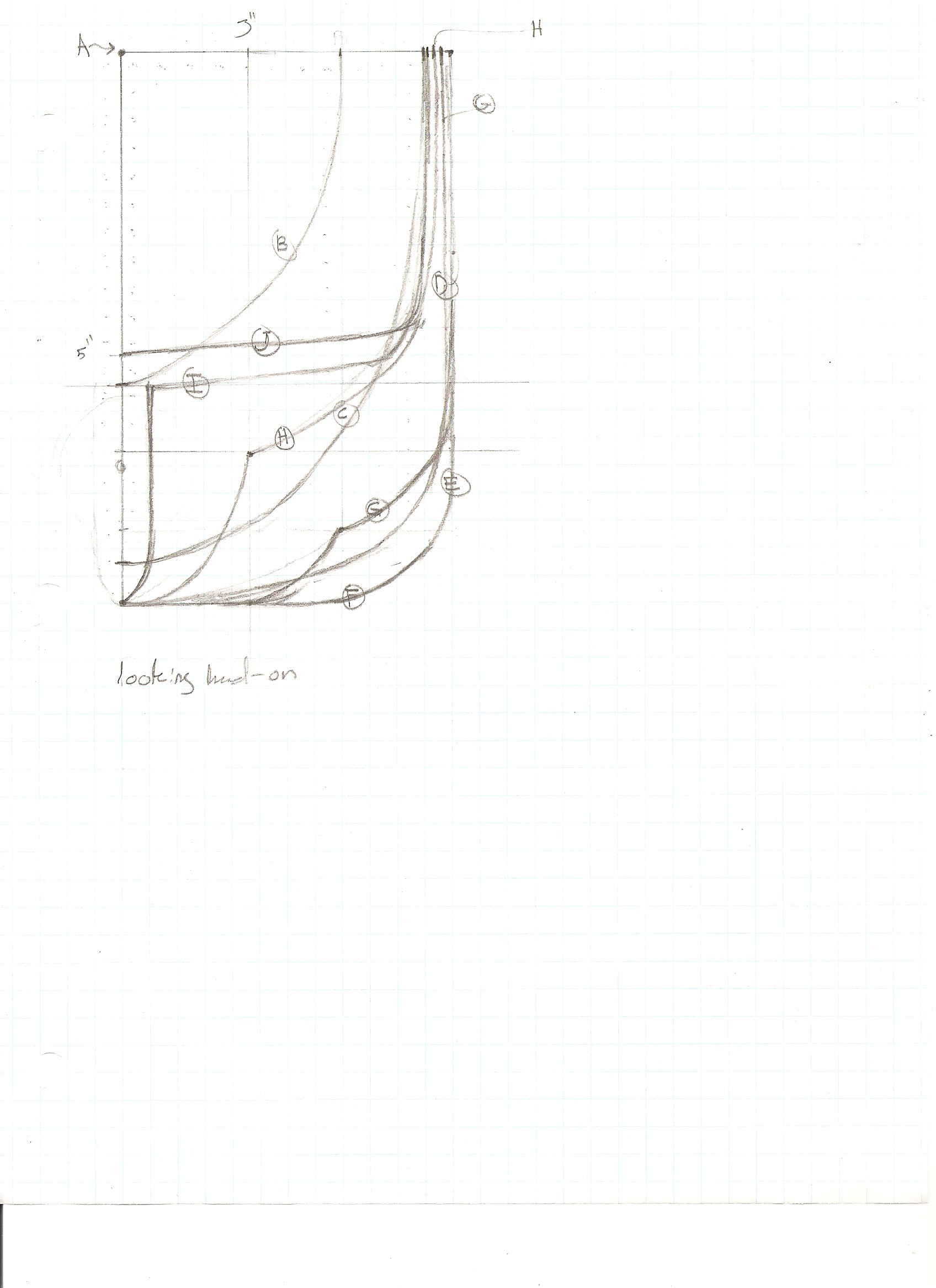
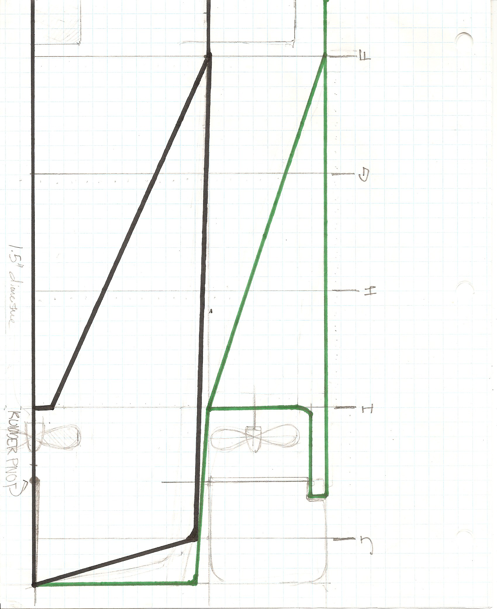
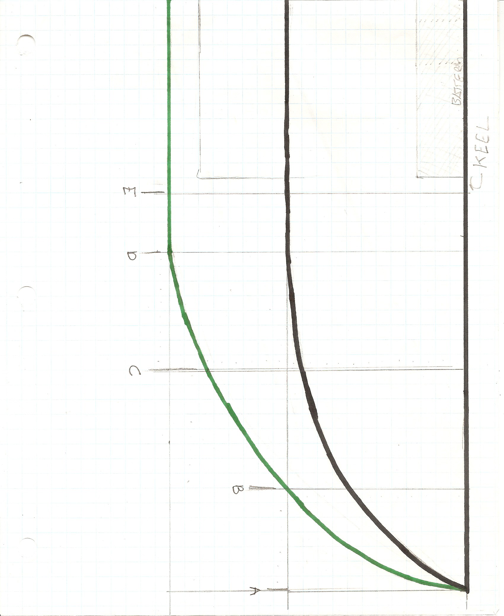
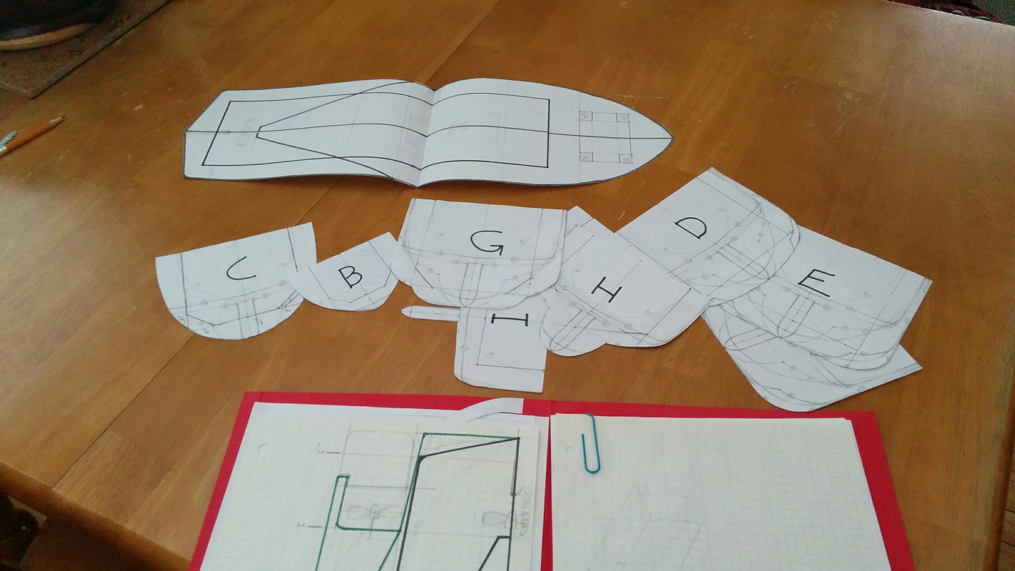
    the design process for the hull was pretty simple. I started by doing a few sketches and picked one that looked like it would work. then I did some full scale drawings:

    there are others, but you get the picture. if you want a full set feel free to contact me. I did the drawings on quarter inch graph paper (I know I should be using metric standards for everything, but its basically impossible to get stock materials in metric sizes) and then scanned them. the second two images are full scale top and side views, they also indicate were each rib is positioned. the green line indicates the bottom edge of the keel (as seen from the side), and the black line is the outer edge of the deck (as seen from the top down). the first image is a cross section that shows the ribs. the letters next to the rib correspond to its position along the keel. to ensure that my designs were symmetrical I copied an mirrored them in the computer. I did this for for the ribs and the deck. from these drawings I produced a series of paper templates for the ribs, keel, and deck:

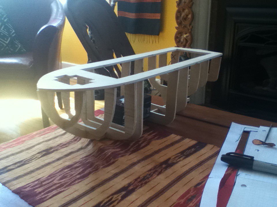
    I used the templates to cut out the appropriate pieces from quarter inch birch plywood. the pieces were then assembled with gorilla glue and some hot glue to hold it in position while the gorilla glue was drying (no actually glued in the below pic but you get the idea):

    in the above picture you can see the battery in place between the E and F ribs. the next stage was planking. there are lots of ways to do this step, and if you're interested in building a model boat I'd suggest doing some reading first, that being said I pretty much picked the easiest/most awful way of doing it.

    to plank the hull I glued strips of pine to the ribs. I used the hot glue and gorilla glue method, in addition to lots of clamping. I don't have any pictures of this processes so you'll have to use your imagination. some of the pieces went on easily as they were covering large flatish surfaces, but the curves were harder. to do the curves I cut lots of triangular pieces individually and then made a copy for the opposing side. the triangles were then glued in place and a 'low-poly' curve was constructed. If for what ever reason you want a full description of the planking process and the associated minutia leave a comment and I'll expand this section, but for now it'll suffice to say I glued lots of little pieces of wood together.

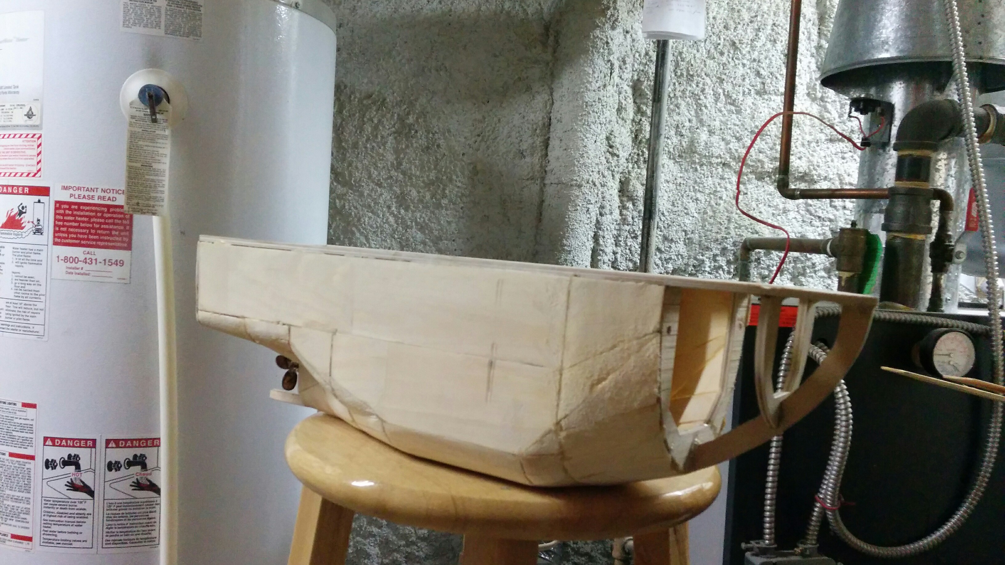
    once the hull was planked and the curves were roughed out I started to file all of the edges down. this process slowly refined the curves on the boat, but it also opened new holes as the planks were ground away. these holes were filled with, glue, wood, and wood filler in a somewhat recursive process until I thought it looked right. here's a pic from that process:

    near the bow of the boat the curve got too steep to continue to build in the method I had been using so I filled the volume between the B rib and the A 'rib' with two solid chunks of ceder and went to town with a bench sander.

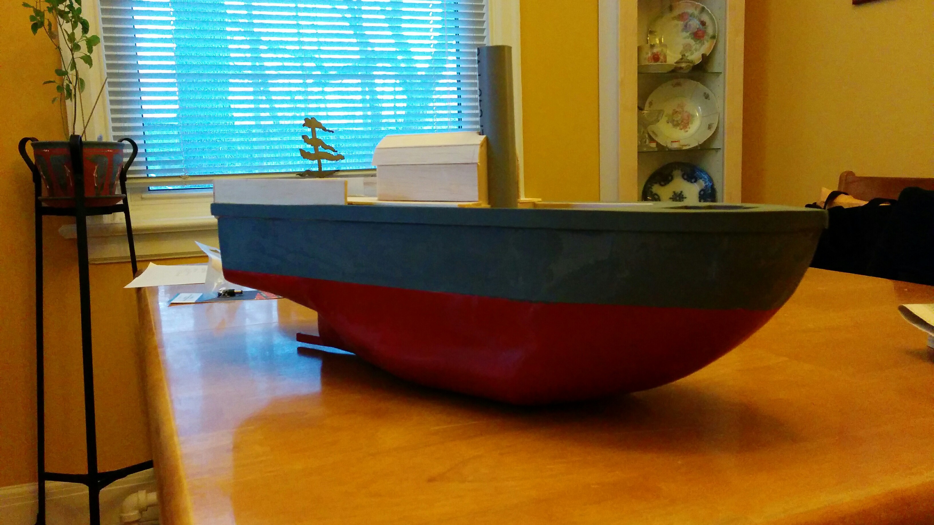
    after the hull was roughed out I applied a few coats of wood filler and sanded a couple more times until the hull was reasonable smooth and uniform. next came paint:

    this pic shows the deck houses under construction, which I'll discuss later. you can see that I also added a railing and gunwale to the boat. After the boat was painted I varnished the outside. I used ~3 coats of spar varnish, but I think any varnish meant to seal out water would probably work. finally to seal the inside of the hull and provide some extra strength I dumped in a couple of cups of fiber glass resin (sans the fiber glass cloth) a sloshed it around until it had covered the interior of the hull. protip: if you're going to use resin on the inside do it before you varnish the hull, if the resin drips on the varnish it'll strip it off.

    that's pretty much it for the hull. I made a bit of a mess with the skeg, but I'll discuss that somewhere else.

View all 4 project logs

Enjoy this project?

Share

Discussions

silvio biasiol wrote 04/14/2016 at 18:14 point

It's a lovely project. The design is pretty neat! I'm building a boat as well if you like this stuff check out mine :)   https://hackaday.io/project/10652-green-powered-sailboat

  Are you sure? yes | no

Similar Projects

Does this project spark your interest?

Become a member to follow this project and never miss any updates