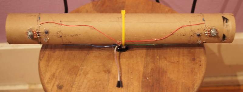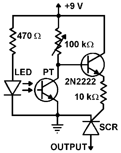
Above is a picture of the first detector prototype. It used a 3" ID packing tube. The sensor tube consisted of 2 emitter-detector pairs at a fixed distance. Each detector output is amplified by a bipolar transistor and the output is used to trigger an SCR.

The circuit used (schematic above) was one I found on this thread - http://www.electro-tech-online.com/threads/stripboard-layout.31418/ however I hadd to adjust component values to compensate for the supply being 5VDC. I used a 330 ohm resistor instead of 470, a 20K pot instead of 100K and a 3.3K instead of the 10K resistor. (The tube contains two trigger circuits.)
The circuit worked well but triggering was inconsistent due to the sensors having a fairly narrow sensitivity. (perhaps 60 degrees?) The mark II prototype uses a narrower tube and shorter distance between sensors to get more consistent triggering.
If you have problems getting it to trigger-
- use a cell-phone camera to check your emitter. (the camera can see the IR)
- to set the sensitivity reduce the potentiometer resistance until the circuit triggers, then back it off a bit.
- too bright of an emitter will prevent the triggering for small/fast projectiles. So if you have problems, try increasing the value of the current limiting resistor to reduce the emitter brightness.
 Alpha Charlie
Discussions
Become a Hackaday.io Member
Create an account to leave a comment. Already have an account? Log In.