GPS Nixie Alarm Clock
GPS controlled nixie alarm clock with IR-receiver
GPS controlled nixie alarm clock with IR-receiver
To make the experience fit your profile, pick a username and tell us what interests you.
We found and based on your interests.
The finished board is now mounted in a metal project box with the front plate replaced with a sheet of tan plexi glass. Originally I wanted to make a nice wooden box for the clock, but since my carpentry skills are somewhat limited and I don't have the necessary tools at hand, I have settled for this simpler solution.
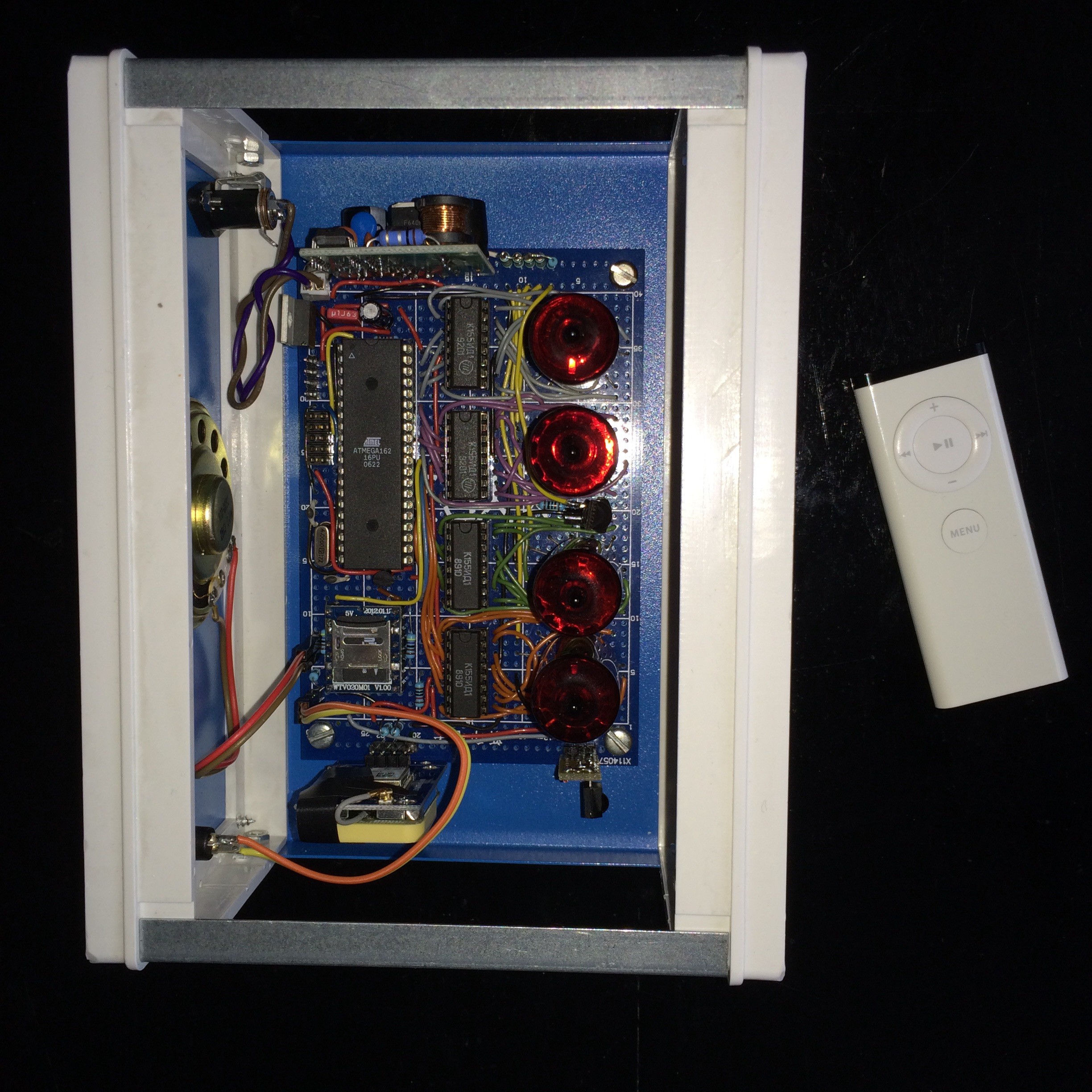
The clock only has one button for snooze / alarm off / display date. All other functions are handled by the Apple remote. The IR receiver is visible at the bottom right.
The red LED has been replaced with a real neon bulb which matches the hue of the nixies.
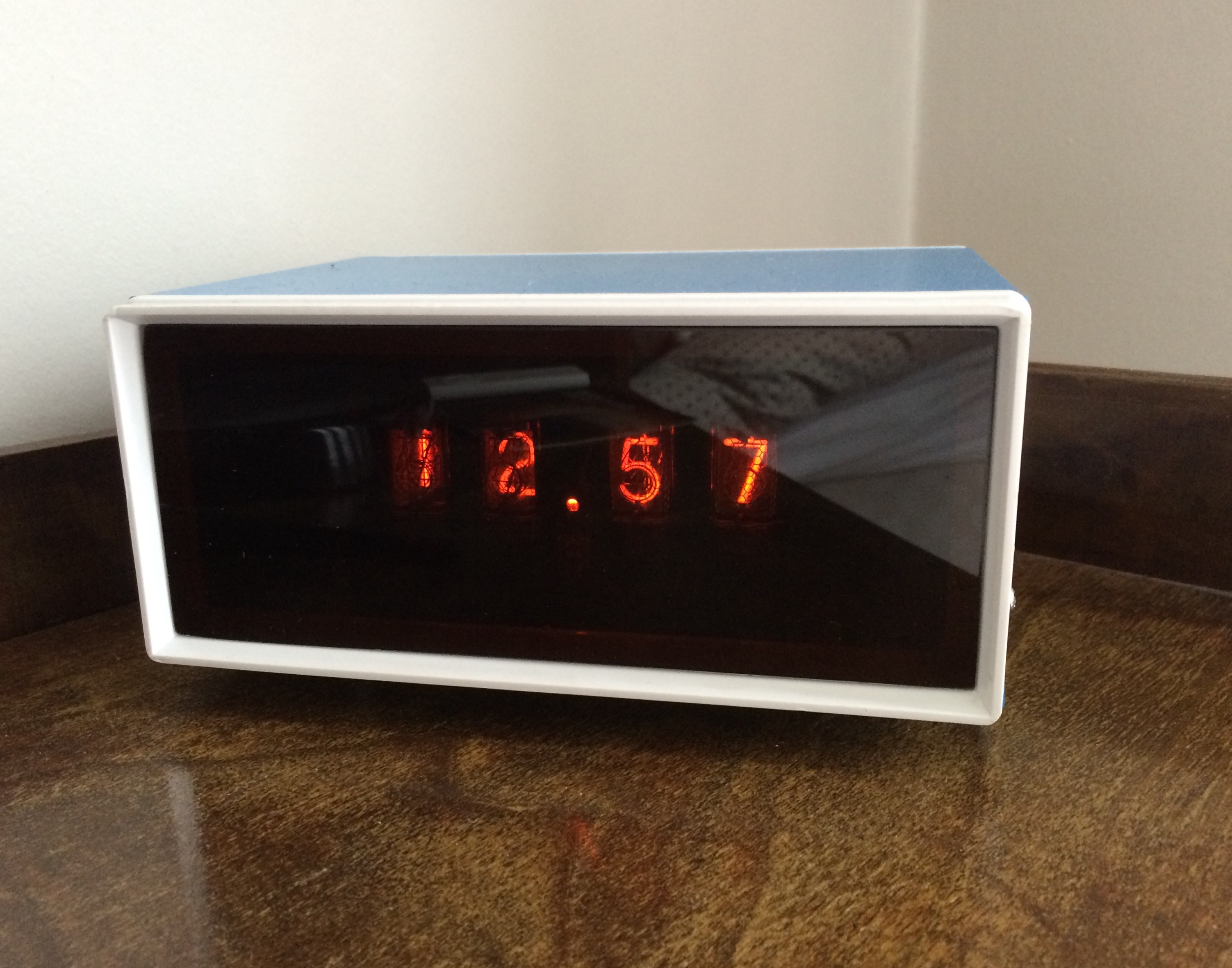
The finished clock.
I thought it could be fun to make the clock able to speak the current time by using the say-command available from the command line in OS X:
NAME
       say - Convert text to audible speech

SYNOPSIS
           say [-v voice] [-r rate] [-o outfile [audio format options] | -n name:port | -a device] [-f file | string ...]

DESCRIPTION
       This tool uses the Speech Synthesis manager to convert input text to
       audible speech and either play it through the sound output device
       chosen in System Preferences or save it to an AIFF fil
I made a shell script to produce audio files with spoken numbers from 0 to 59 and converted them to AD4.
Using this small routine, the clock speaks the current time when the play/pause-button on the Apple remote is pressed:
/*
 * Speak current HH and MM using voice files from 0 to 59 starting at position 400
 */
void say_clock()
{
	// hours
	wtv020_cmd(400 + lcl_time->tm_hour);
	_delay_ms(1000);

	// extend delay for long hour numbers
	if (lcl_time->tm_hour > 20)
		_delay_ms(500);

	// leading zero when single digit minutes
	if (lcl_time->tm_min < 10)
	{
		wtv020_cmd(400);
		_delay_ms(600);
	}

	// minutes
	wtv020_cmd(400 + lcl_time->tm_min);
	_delay_ms(1500);

	// silence
	wtv020_cmd(0xffff);
}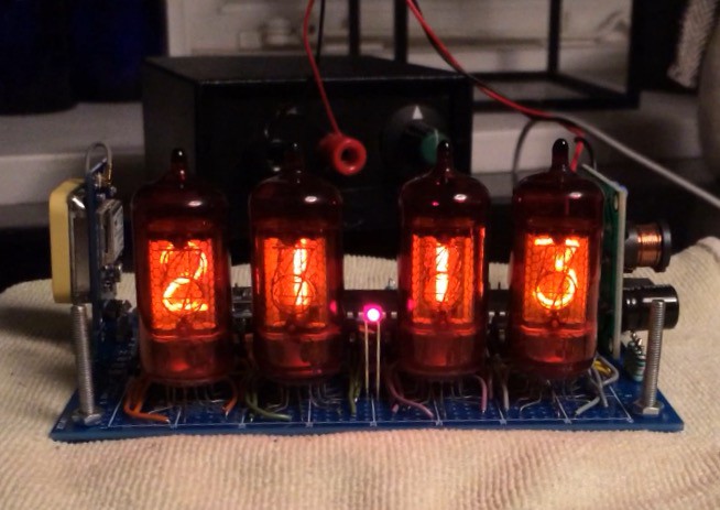
Board updated with GPS module, and now the clock works. The LED is on when GPS fix is obtained, and flashes at 1 Hz when no signal is received. TIMER1 is configured to overflow every second, and a timer interrupt is set up to call system_tick() so the clock is running when there is no GPS signal.
The firmware for the clock is written in C using Eclipse C/C++ with the AVR Eclipse plugin with avr-gcc and avr-libc 1.8.1
Since the GPS module provides the time in UTC, I need to handle time zone and DST in software. This is actually quite easy since the standard time.h functionality has been implemented in avr-libc 1.8.1. But as I started the development on Linux using 1.8.0 it took me a while to discover the newer avr-libc since there are still no official binary packages for avr-libc 1.8.1 even though it was released more than a year ago.
After moving to OS X it was quite easy to get avr-libc 1.8.1 with macports.
In version 1.8.1 it is simple to initialize the time routines:
	// time zone hardcoded to UTC+1
	set_zone(1 * ONE_HOUR);

	// enable european DST
	set_dst(eu_dst);
Yeah, it's pretty lazy to hardcode the time zone when I have a full blown GPS receiver available, but the ATmega162 only has 16 KB flash and 1 KB RAM, I opted not to implement GPS coordinate to time zone conversion to save the limited resources for other features.
While searching for suitable device capable of playing alarm sounds, I found the WTV020SD-16P:
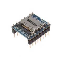
Small footprint, integrated micro SD card slot, able to drive a small speaker directly and controlled with a simple two-wire interface. This module is a perfect fit.
But it does have a few quirks:
First, the module is VERY picky about which SD cards it will read. It didn't work with the no-name 2 GB card I received together with an SD adapter. Fortunately I found another 2 GB card in an old phone, and that did work.
Second, it only works with the odd AD4 file format.
More about that here:
http://www.buildcircuit.com/how-to-use-wtv020sd-music-module-with-arduino/
So it is necessary to convert MP3 or WAV files to AD4 using one of the tools mentioned in the article. If anyone knows more about the AD4 format or any open source conversion tools, I would like to hear about it.
When I started the project, it seemed natural to just use DCF77 for time syncronization as this has more or less been the de-facto method for radio controlled clocks here in Europe.
So I just ordered a DCF77 receiver module with included ferrite antenna. I assumed it would be pretty simple to get a signal and decode it, but I never managed to get a stable signal from the receiver.
To be honest, I didn't try that hard... I suddenly remembered having a DCF77 controlled alarm clock many years ago, and why that particular clock is no more. It took forever to sync the time when turned on, and it could suddenly be off by several hours.
Apparently the DCF77 signal is quite susceptible to radio interference and the one bit pr. second protocol feels pretty antiquated today.
So, enter the Ublox NEO6-M GPS module:
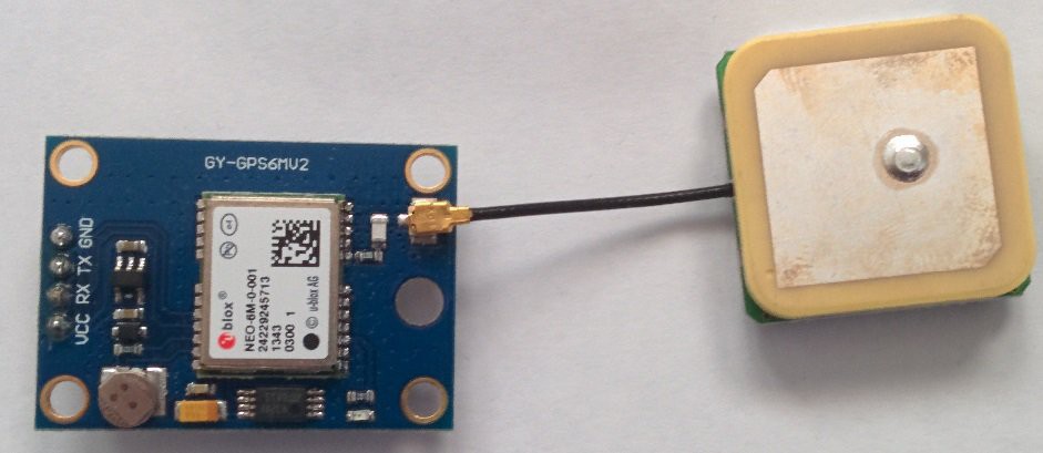
These modules are dirt cheap, small, come with antenna, and have a simple RS232 interface and use a standard protocol (NMEA). What's not to like?
Luckily, I used an AVR with an extra UART.
One module ordered, took forever to arrive, but now hooked up in a test setup:
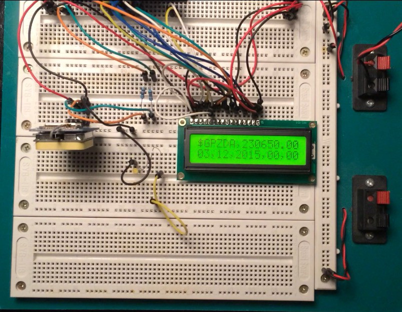
Much easier, faster and stable than DCF77.
However, it does impose a couple of challenges: The GPS time information is UTC only. The ZDA message should be able to provide local time information, but I have not been able to get my module to provide any information in those fields. So time zone and DST must be handled in software, more on that later...
Hardware-wise there are two issues:
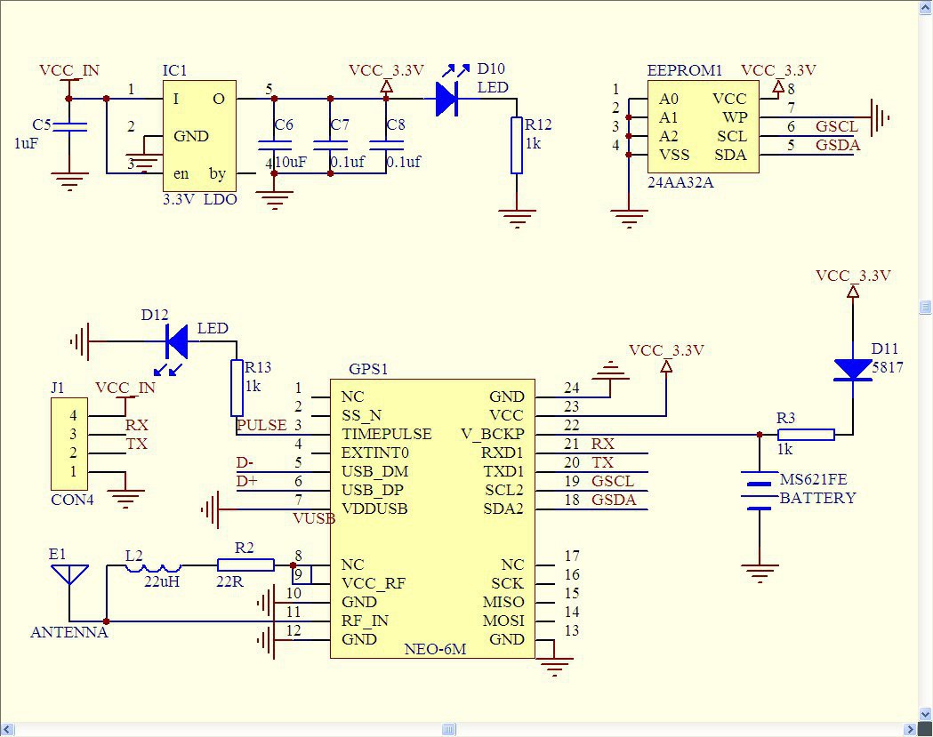
The Ublox chip is 3.3V and the board has a 3.3V regulator, but there are no level converters on the board for the RX/TX lines. Since my main board is 5V, I can't just connect the lines directly to the ATmega162. I solved the issue the quick'n'dirty way with two 10k resistors, it works fine.
Another issue is that the board has an obnoxious blue LED which flashes at 1 Hz when the module has GPS fix. I have managed to turn it on permanently with a certain UBX command string, but I have not managed to turn it off. If anyone knows how to to this with the UBX protocol, I would like to hear about it. Yeah, I could just desolder the LED from the board, but it is so damn small, so for now I have just covered it with a patch of duct tape :-)
After receiving the last two nixie driver IC's, and finally being able to run all four tubes, it turned out that my crude breadboarded HV PSU wasn't quite up to the task. The inductor on the PSU was getting very hot and the HV supply was sagging trying to keep the tubes lit.
It turns out that LV to HV switch mode PSU design is not that trivial if you want an efficient design, and hacking such a PSU together on a piece of breadboard is definately a no-go.
Instead of wasting more time on making a proper HV PSU, I ended buying a kit like this:
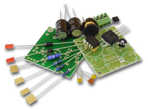
The kit arrived a few days later and with that assembled and having replaced the old PSU, all four tubes where lit without any problems or excessive heat.
While waiting for the last two KM155ID1's to arrive, I implemented a simple counter in order to further test the nixies and the drivers:
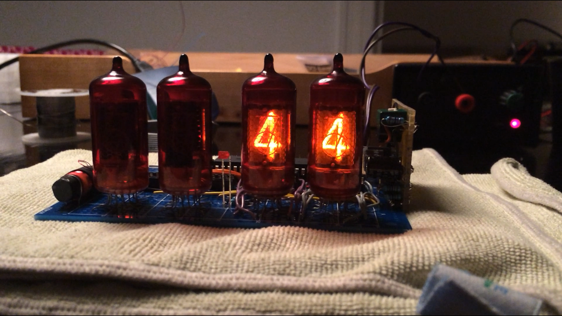 It would have been possible to use only two or even just one nixie driver IC if I had chosen a multiplexed driver design. But since multiplexing the tubes could potentially lead to problems with high-pitched noise from the PSU or the tubes themselves, and since the clock is to be placed right beside the bed, I have opted for simple non-multiplexed driver circuitry necessitating a driver IC for each tube.
I have not been able to find conclusive information on whether a multiplexed design vs. a non-multiplexed design has any impact on tube life.
One downside to using a non-multiplexed design is that it is not possible to dim or control the brightness of the tubes. This will have to be done with an optical filter.
I decided to use an ATmega162 for the clock as I allready had a couple of those lying around. They were originally bought for another project many years ago. ATmega162 differs from ATmega16 mainly in having two UART's. First I only needed one UART for debugging purposes, but later it turned out that having two UART's was actually necessary.
In another junk pile I found an unused breadboard PCB with suitable dimensions for the project.
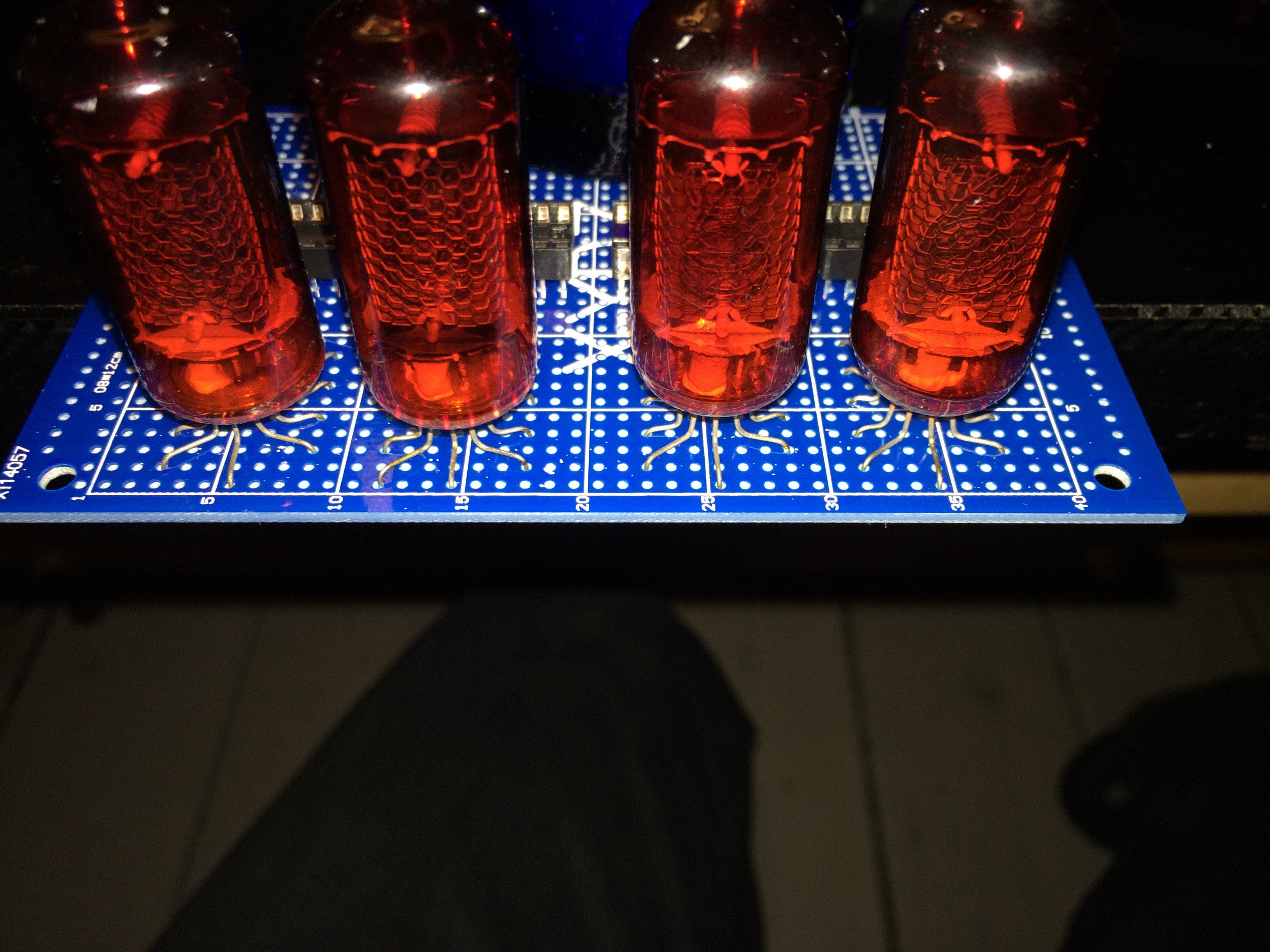
Test mounting of the tubes:
Initial layout of the board:
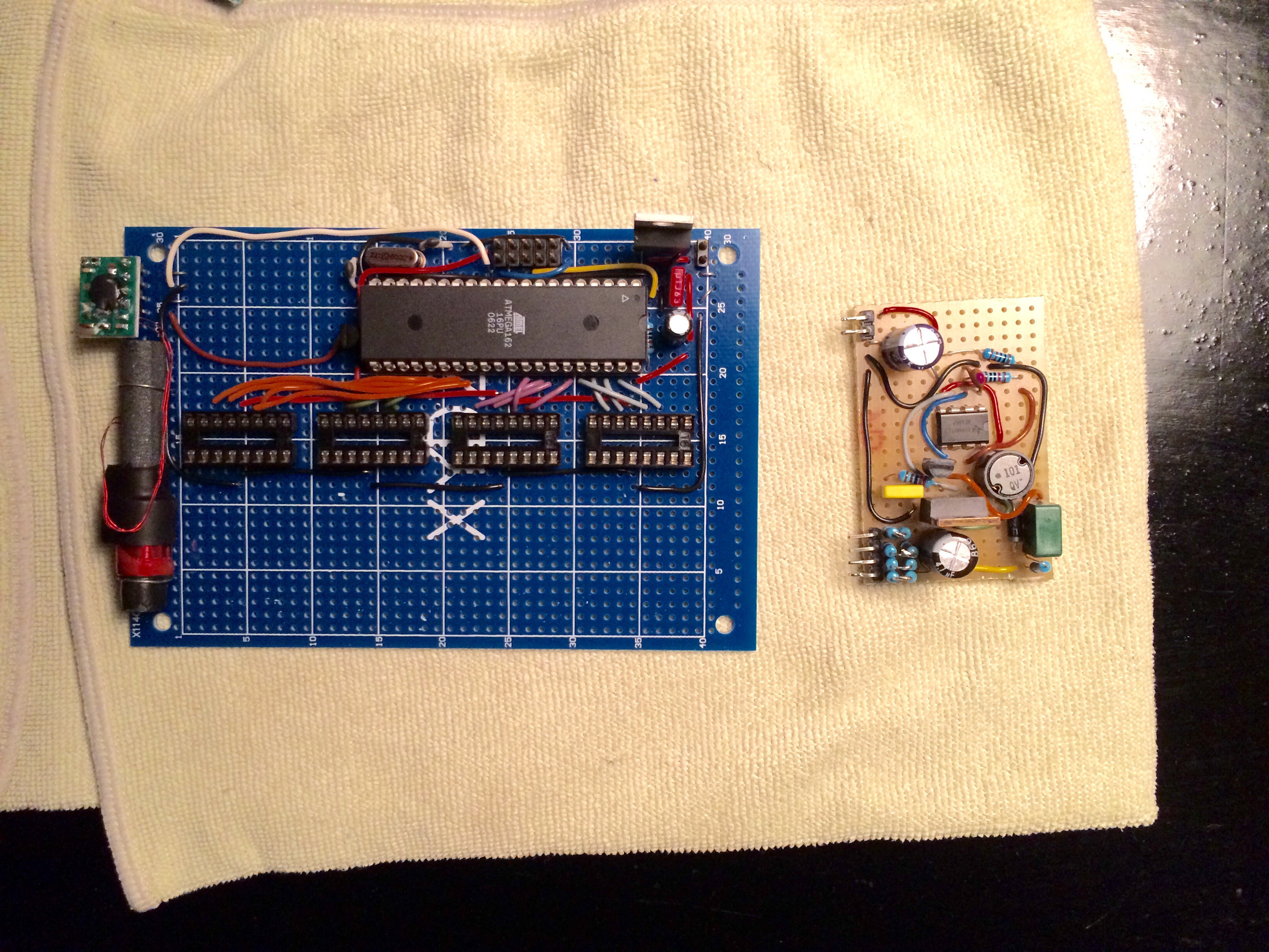
Voltage regulator, MCU and sockets for the nixie drivers mounted. The DCF-77 receiver I first planned to use for time sync on the left, my crude HV PSU on the right.
The first challenge would be finding som usable nixie tubes. Judging from various searches, it seems like the most common tubes are the russian made IN-14 or the large IN-18.
The IN-18 looks pretty awesome, but since building nixie based clocks apparently has become quite popular, finding IN-18's for sale with a reasonable price tag seems impossible.
The IN-14's would be fine if it wasn't for the fact the "5" is a "2" mounted upside down, which I don't like.
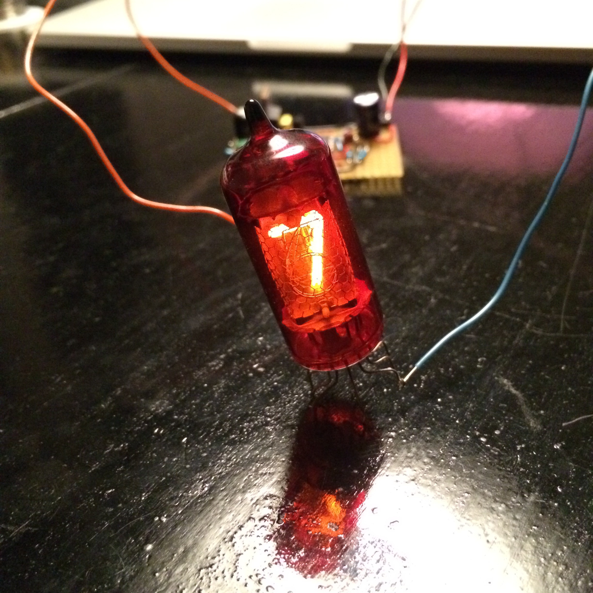
But then I stumbled upon a package deal with 6 x Z570M tubes on eBay. They have a real "5" and they are coated with a red filter. Perfect.
Upon arrival I wanted to test the tubes by building a HV PSU capable of delivering the 170 VDC neecessary to light the tubes. On the web I found a simple 555-based circuit which I built on a small breadboard PCB.
Create an account to leave a comment. Already have an account? Log In.
I have not had any issues with GPS reception even though the enclosure is partly metal. The clock normally sits in a window, but even in the basement it synced just fine.
Become a member to follow this project and never miss any updates
By using our website and services, you expressly agree to the placement of our performance, functionality, and advertising cookies. Learn More
Working on a similar project, I'm wondering what the GPS reception is like, as the watch will sit indoor ? Any issues synchronising ?