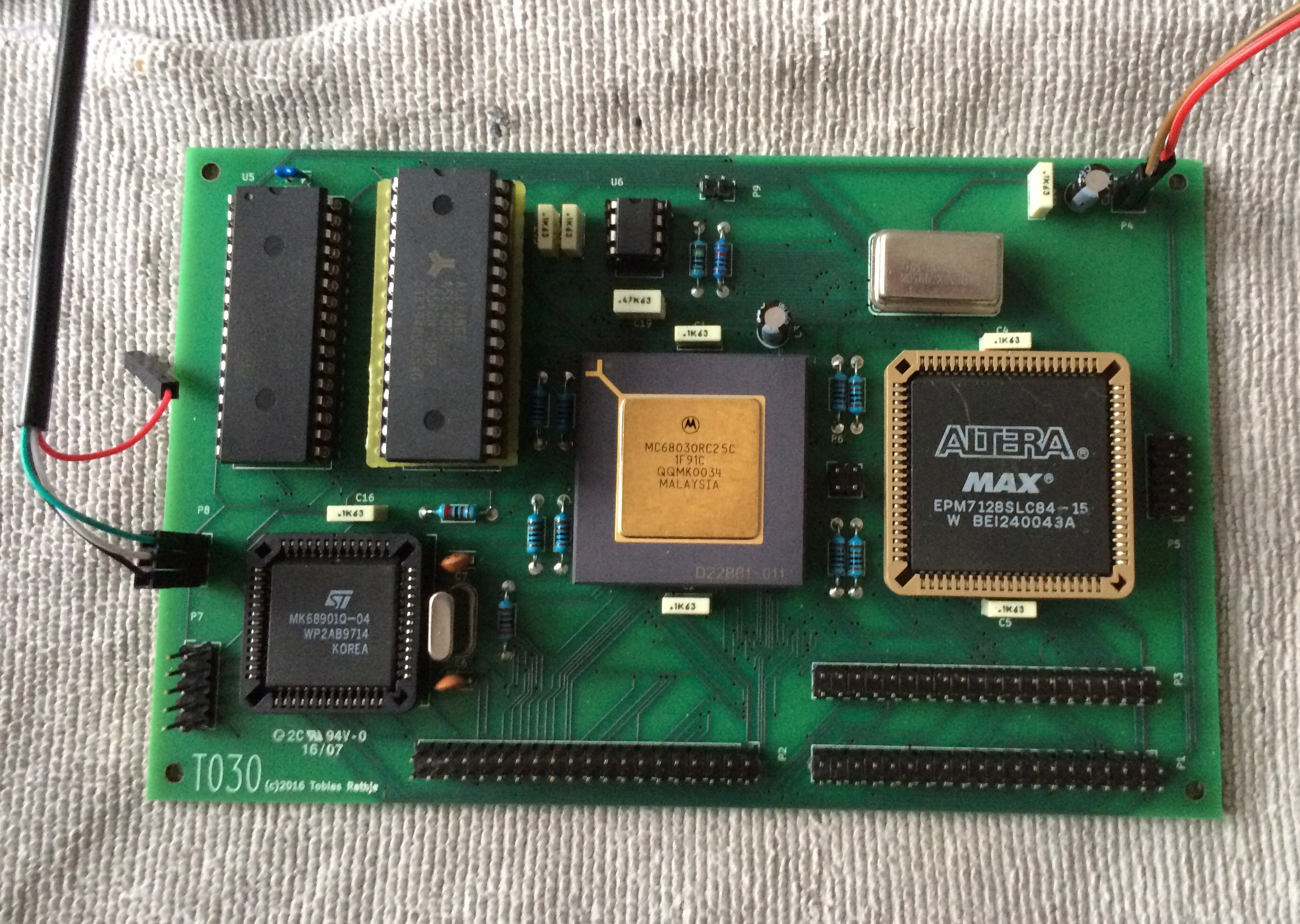
The board is now fully assembled:

Notice the adapter I had to make to correct my design mistake with the RAM address bus. Apart from that It's very satisfying to see the finished board, as this is my first real PCB design.
But does it actually work?
To test the board, I have borrowed the monitor program from Jason Westervelt's 68020 project: https://hackaday.io/project/8725-rhombus
As my hardware and glue logic is a little different than that from the original application note from Motorola, I have changed the base addresses for the ROM, RAM and MFP.
The first attempt to fire up the board didn't result in any output on the serial port :-(
The logic analyzer revealed that the processor was indeed alive and executing instructions, so far so good. But it was stuck waiting for an empty transmit buffer on the MFP, hmmm... The scope showed no output from timer D and C on which the serial port depends, so maybe the MFP wasn't getting properly initialized.
After going through my schematic and the data sheet for the MFP, I discovered another design glitch: The register select lines for the MFP (RS1-RS5) are supposed to start from A1 and not A0 as I have done. I assume this is for compatibility with the 68000 without dynamic bus sizing. But this should be no problem on my 68030, so I can just omit the one byte spacing between the MFP register.
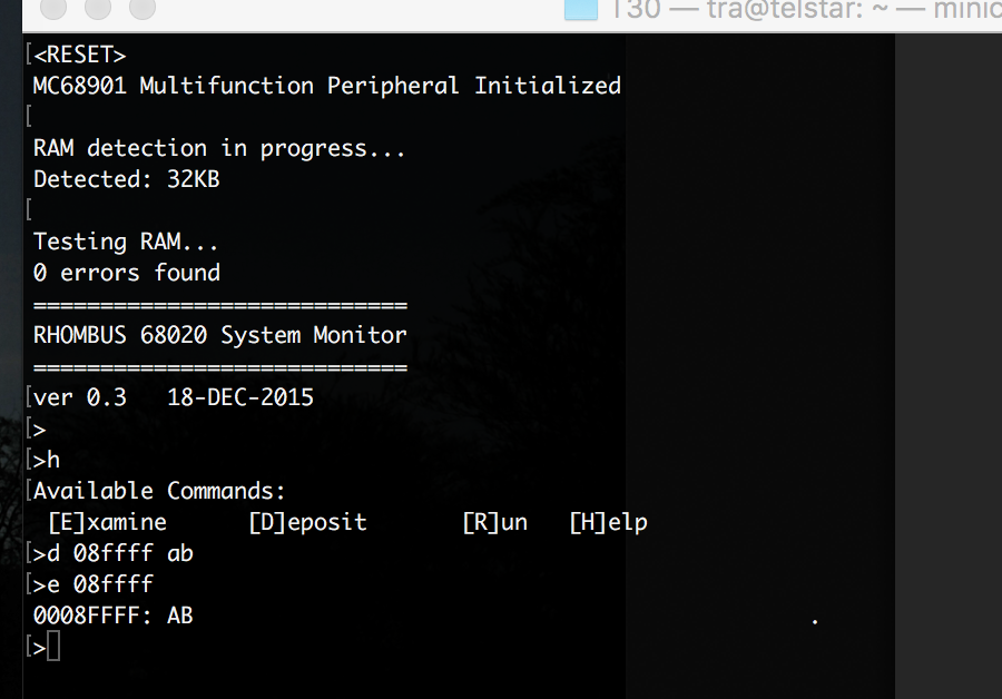
Second attempt:

Woohoo, it's alive! :-D
I have yet to find out why the memory detection only shows 32KB as I have 512KB and it all appears to be addresable and functional.
As the monitor program allready has TRAP 15 routines defined to be compatible with the Easy68K simulator it should be pretty straight forward to get EhBasic running on my board.
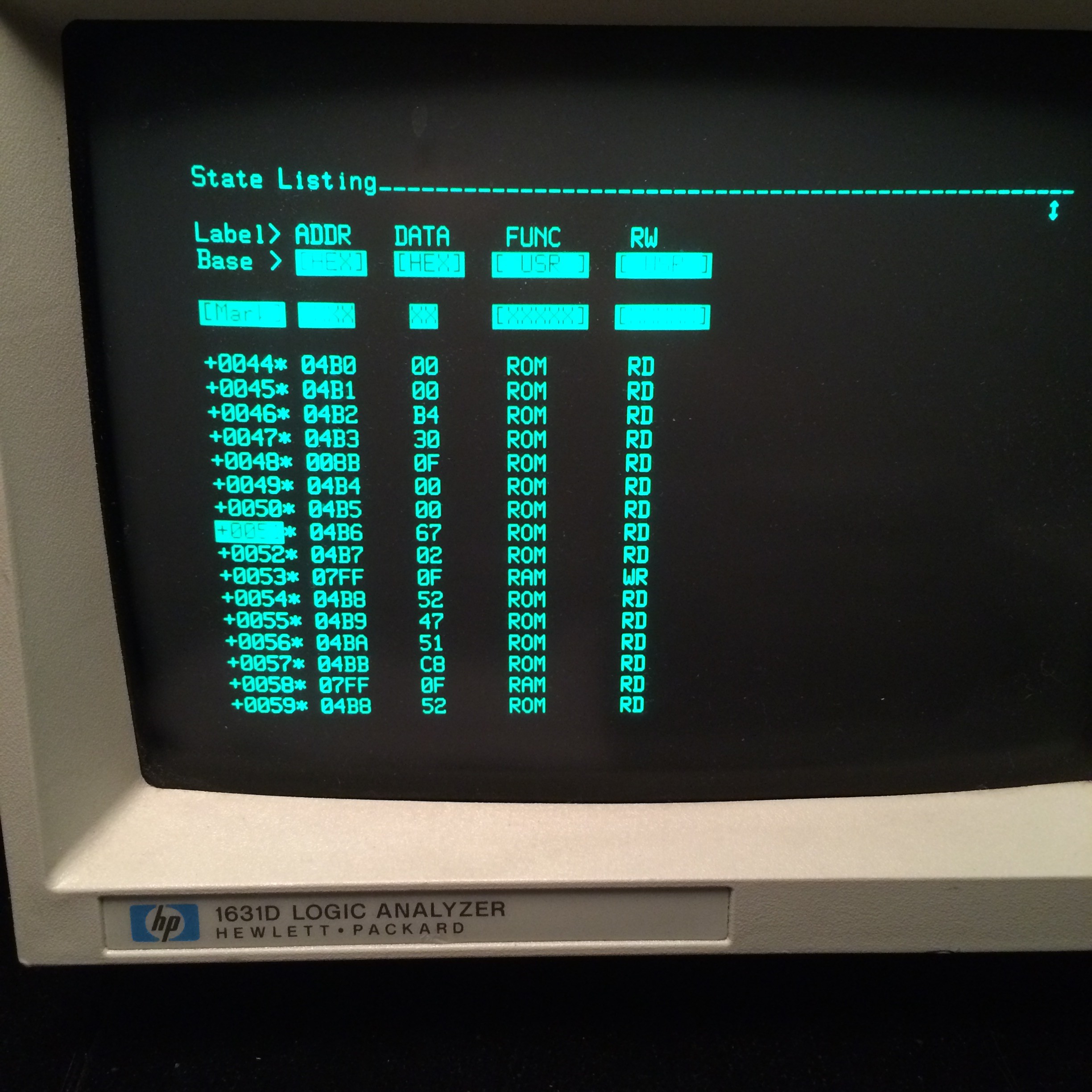
The first attempt made it to the "Ready" prompt, but it didn't react to any input on the console. After some debugging I found an error in a conditional branch in the trap code resulting in an invalid instruction exception. Once again the old HP dinosaur with its state listing was incredibly handy in figuring out what the processor is actually doing. Here shown during the initial RAM test:

With the trap code fixed:

The next step will be to setup a cross-compiler toolchain based on gcc and probably the newlib libc implementation, and try to create my own monitor, trap code and exception handlers. I have an idea that I will try to hook up an SD card to the GPIO pins on the MFP and implement a FAT32 library so I can load stuff easily.
Btw, I am quite surprised at the modest power consumption of my board. I was worried that I had screwed up the power distribution to the processor with way too narrow tracks, but the board in its current state only draws about 250 mA when running code and outputting stuff on the serial port. It should be noted that currently I am only running the processor at 12.5 Mhz, so I guess it will draw more current running at full 25 Mhz.
 Tobias Rathje
Discussions
Become a Hackaday.io Member
Create an account to leave a comment. Already have an account? Log In.