Close
0%
0%

LiFePO4wered/Pi

LiFePO4 battery / UPS / power manager for Raspberry Pi

Similar projects worth following
- Ever wished you could unplug your Raspberry Pi and move it elsewhere when you were in the middle of something and didn't want to turn it off?
- Ever wanted to have your Pi run on battery power for a couple of hours?
- Ever wanted to have your Pi sleep most of the time, but wake up to do a short task at regular intervals, all while battery powered?
- Ever wanted your Pi to have a power button that would do a clean shutdown instead of just pulling power, even when you were using it headless?
- Ever had a high-availability application where you wanted your Pi to run through short power outages, and cleanly shut down and come back online when power returned?

If you answered "yes" to any of these questions, the LiFePO4wered/Pi or LiFePO4wered/Pi3 are for you! :)

The LiFePO4wered/Pi and LiFePO4wered/Pi3 can now be bought on Tindie:
https://www.tindie.com/stores/xorbit/

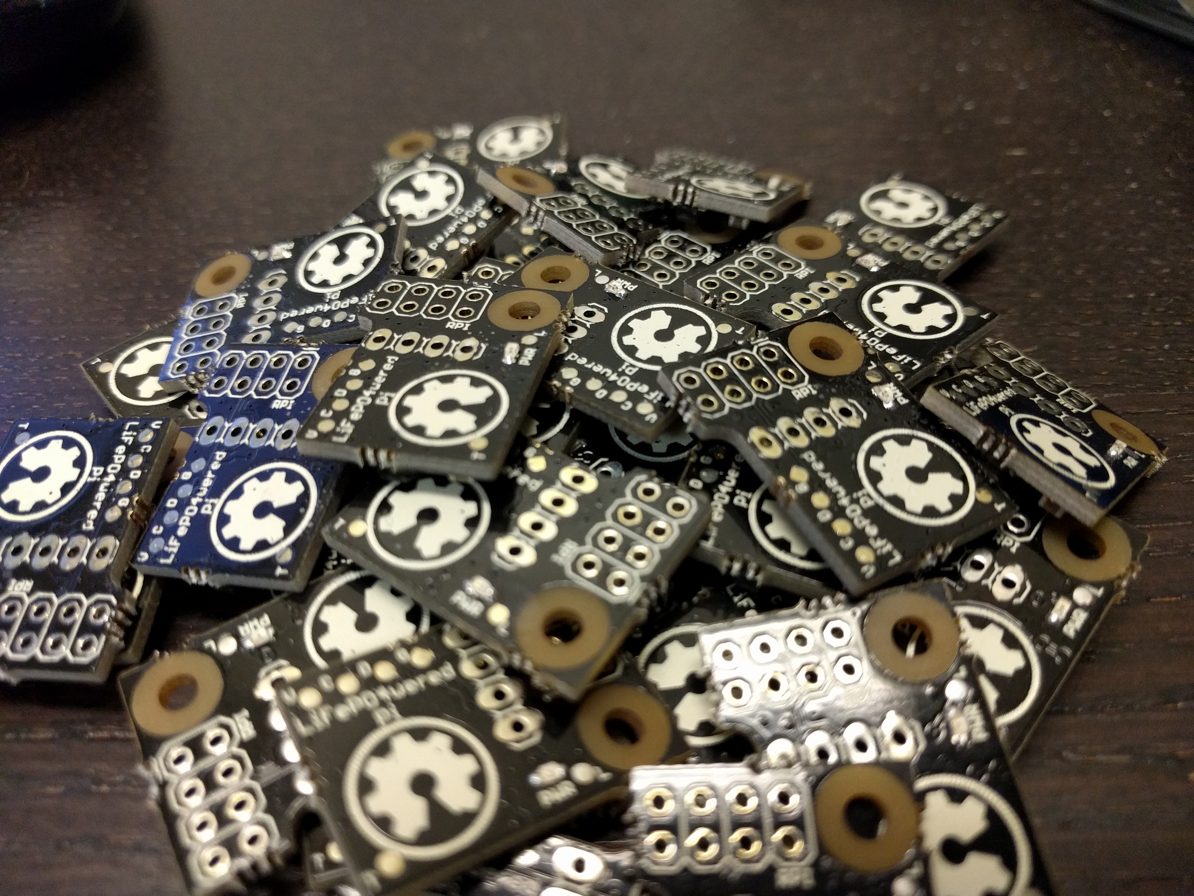
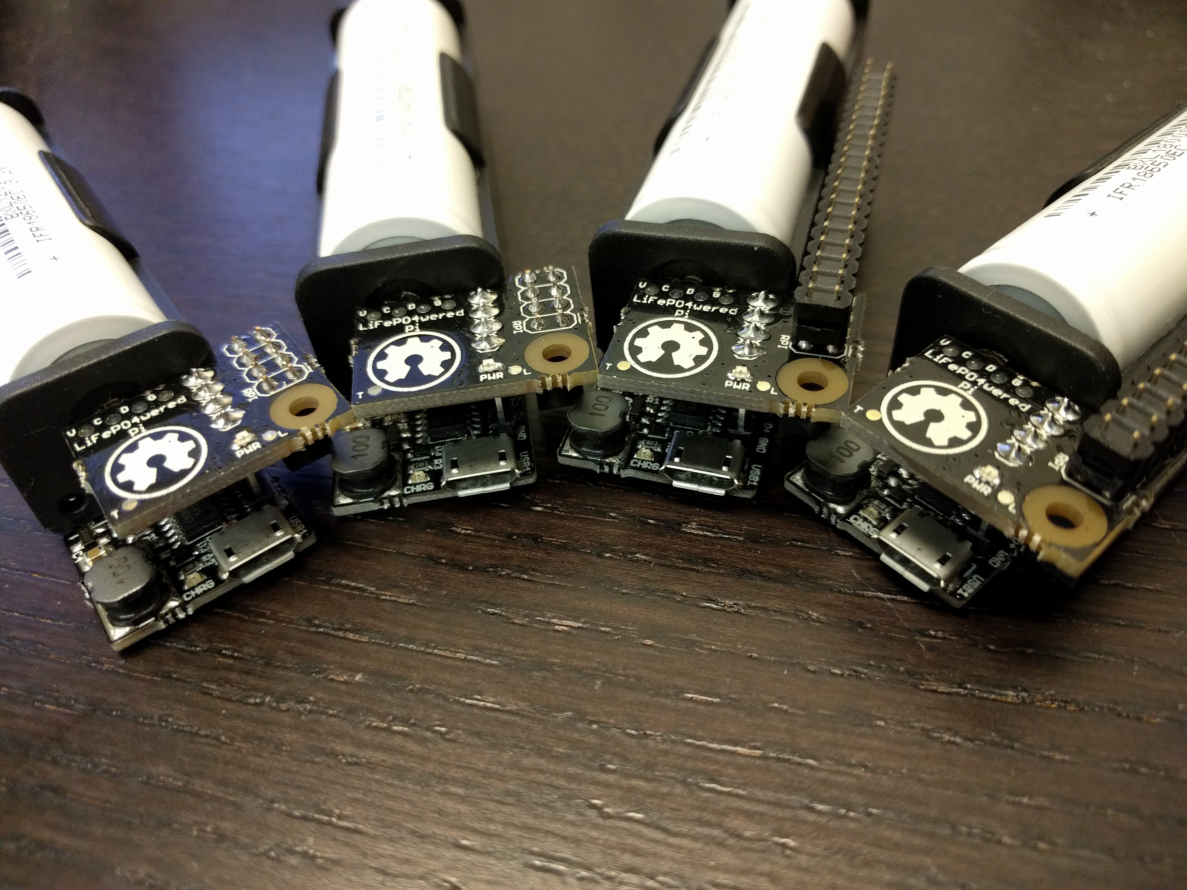
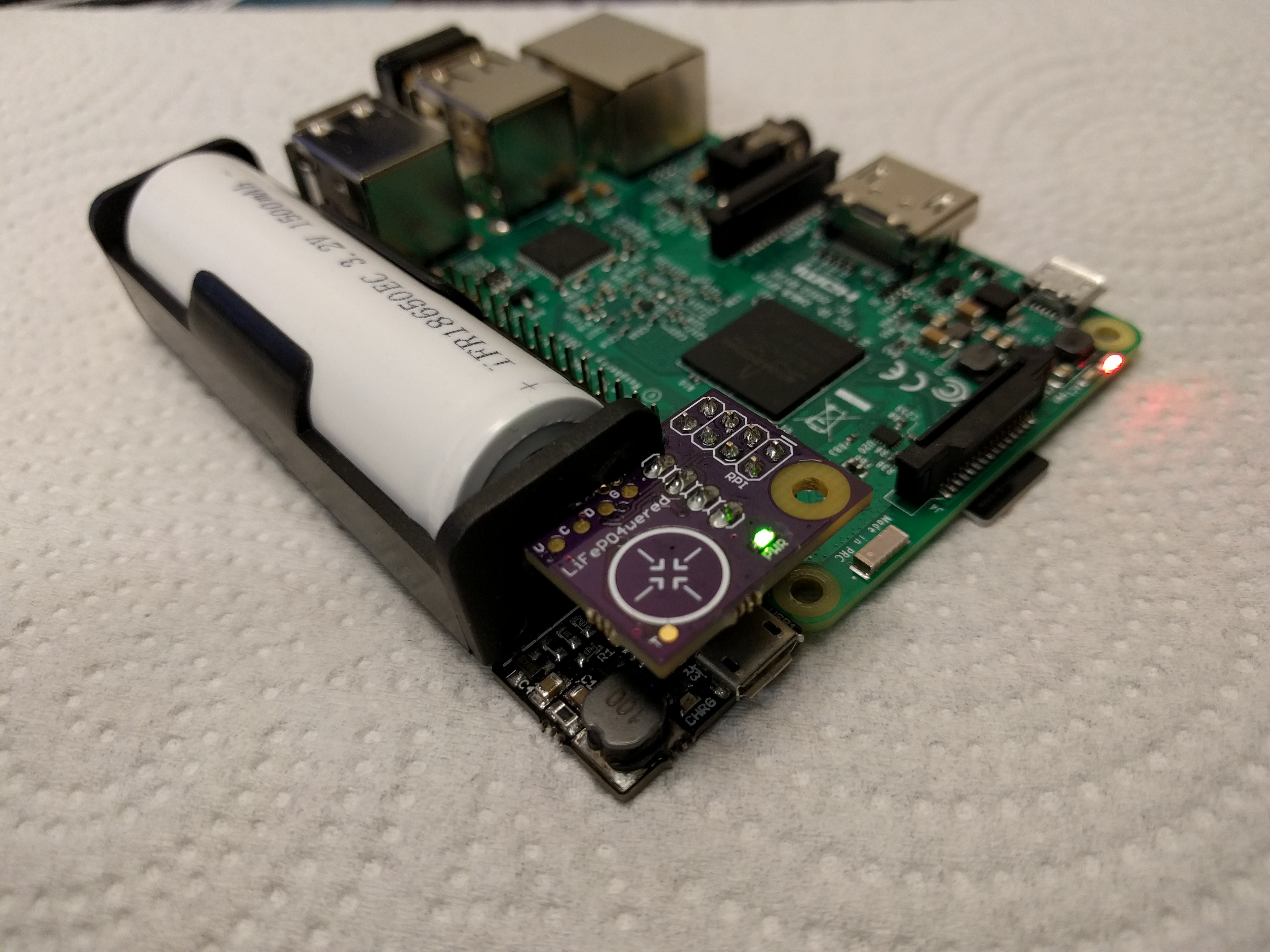
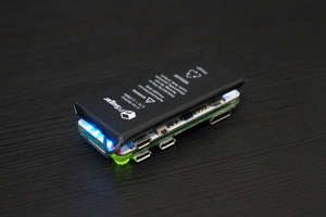
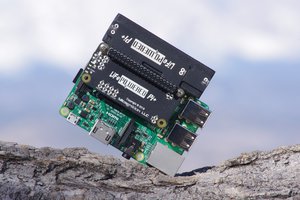
The project is built on top of a LiFePO4wered/USB or #LiFePO4wered/18650 module. A small board is added with an MSP430G2231 microcontroller that takes care of monitoring input and output voltage, monitoring a PCB touch button, driving a power indicator LED and switching the load (the Raspberry Pi power). The microcontroller is also connected to the Pi's I2C bus and monitors the Pi's running state. The small board connects to 8 of the Pi's GPIO pins but leaves the rest free to allow prototyping using fly leads.

An Open Source software package is provided on the Raspberry Pi to interact with the LiFePO4wered/Pi. It contains a library that can be used in your own applications, a CLI interface to read and write device registers over the I2C bus and a tiny daemon that continually tracks the power state, and can initiate a clean shutdown when the battery is empty or the user wants to turn the Pi off using the touch button. Touch button parameters, voltage thresholds, auto boot settings, wake timer and auto shutdown timer (#LiFePO4wered/18650 version only) can be customized by the user and saved to flash.

The touch button requires press-and-hold to turn the Pi on and off to prevent accidental activation. The power LED indicates several power states: off (LED off), busy with boot or shutdown (LED breathing), on (LED solid on). The LED also provides touch button feedback: fade on during the press-and-hold delay, fast flashes when the LiFePO4wered/Pi cannot comply with the user input, either because the input voltage is too low or the Pi is busy booting or shutting down.

Normally the LiFePO4wered/Pi will wait for the user to press the button before it will boot the Raspberry Pi. Auto boot values can be set over the I2C bus so the Pi will automatically boot whenever there is enough battery charge, or when the USB voltage is present (#LiFePO4wered/18650 version only). There is also a wake up timer that can be set so the Pi can shut down, and automatically be started again after the wake timer expires. There are separate, customizable thresholds voltage levels for when the Pi is allowed to boot and when it will be instructed to shut down, or even forcefully turned off in case the daemon isn't active or fails to shut down the Pi. This ensures stable operation and over-discharge protection for the battery.

Based on testing with different Raspberry Pi's, a Model A+ and Pi Zero are able to run from the battery for over 2 hours. The B+, B2 and B3 take more power, but should be able to run for at least an hour. Run time will of course depend on system load as well. For UPS use, the #LiFePO4wered/USB based version is limited to low load conditions with the Pi Zero or Model A+, the #LiFePO4wered/18650 based version is recommended for UPS use in higher load conditions.

LiFePO4wered-Pi-5V.pdf

LiFePO4wered/Pi 5V version schematic

force-download - 19.90 kB - 03/14/2016 at 15:06

Preview

LiFePO4wered-Pi.pdf

LiFePO4wered/Pi 3.2V version schematic

force-download - 18.15 kB - 03/14/2016 at 15:06

Preview

  • 1 × LiFePO4wered/USB (MCP73123-22JI version - LiFePO4wered/Pi) USB chargeable LiFePO4 power module
  • 1 × LiFePO4wered/18650 (LiFePO4wered/Pi3) High power USB chargeable LiFePO4 power module
  • 1 × MSP430G2231 Ultra low power microcontroller, 2K flash
  • 1 × MIC2876 (5V version) Boost regulator with bidirectional load switch
  • 1 × AP22802 (3.2V version) Bidirectional load switch

  • Hardware, firmware, software update

    Patrick Van Oosterwijck01/07/2018 at 19:32 1 comment

    I've been very busy with the development of of the #LiFePO4wered/Pi+ lately, so updates here have been sparse, my excuses for that.  That doesn't mean that nothing has been happening though!  In fact, much of the development going on for the /Pi+ also benefits this project directly, since there is a large shared code base that has been extensively tested on both devices.

    Let's go over what's new:

    Hardware

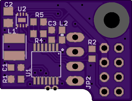
    The new layout with the improved footprint for the MIC2876 boost converter has been working very well, I have had much less assembly issues with this new batch.  Lesson learned: don't just pick a footprint from the library that looks right, instead make sure it's as close to the manufacturers recommendations as possible or make your own!

    The new layout also has a new design for the touch button:

    How do you guys like it?  And what it means?

    I've been a little remiss on making true on the meaning of that logo, sorry about that.  But very soon now, the source Eagle files for the LiFePO4wered/Pi and #LiFePO4wered/18650 (which is the charging base for the LiFePO4wered/Pi3) will be put up on GitHub! Yay! :)

    Firmware

    Much work has been done on firmware in the last couple of months.  The LiFePO4wered/Pi and #LiFePO4wered/Pi+ share a code base, so improvements made for the one directly benefit the other as well.  Here is a summary of the improvements that have spilled over to the LiFePO4wered/Pi:

    • I2C write shadow buffer.  This ensures multi-byte register values are always written atomically to prevent race conditions.  The I2C peripheral on the MSP430G2231 is a pain because it requires so much babysitting in software, and the Raspberry Pi's I2C peripheral is a pain because it doesn't support clock stretching.  Initially I had a shadow buffer for both read and write, but because the bytes coming out of the LiFePO4wered/Pi could never be 100% trusted (the first bit might be wrong because the software couldn't get to it in time), ensuring consistency for reads has been shifted to the Raspberry Pi code, and only the I2C write shadow buffer is left.
    • I2C write unlock code.  To prevent erroneous register writes when multiple processes are trying to access the LiFePO4wered/Pi, a write now needs to be preceded with an unlock code.  Look at the host software source or the updated product brief for details.
    • Timeouts for boot and shutdown states.  Before, the LiFePO4wered/Pi would stay in these states until the right host event occurred.  But if a Pi became unresponsive, these events wouldn't happen and the LiFePO4wered/Pi would just keep waiting.  Now the timeouts ensure the power is turned off eventually if things are unresponsive.  The timeouts can also be adjusted by the user.
    • It is now possible to force the power output off by pressing and holding the touch button for 10 seconds.  Nice for when you have started the LiFePO4wered/Pi without a Pi attached or if you have forgotten to insert an SD card.
    • If the user wants to connect a hardware button, this was already possible by connecting a button in series with a 100pF capacitor between the T and G pads.  Since support for mechanical buttons was added for the #LiFePO4wered/Pi+, this is now also available on the LiFePO4wered/Pi.  Just set TOUCH_CAP_CYCLES to zero and connect a button between the T and G pads, no capacitor needed in that case.
    • ADC values now have more precision.  I already was doing a running average on the ADC readings, but now instead of scaling this back to 10-bit every time, I keep the 13-bit value.  The result is better filtering, and less code.
    • Added a host application watchdog function.  When using this feature, your application needs to regularly reload the watchdog timer so it doesn't run out.  If it fails to do so, the watchdog timer will expire.  When it does, either the LED will start flashing an error pattern to let you know, or the system will be shut down. ...
    Read more »

  • Some you win, some you lose

    Patrick Van Oosterwijck10/18/2017 at 15:41 0 comments

    In this case I lose.  Twice actually, since this is the second time I'm posting this!  Not sure what happened to the first attempt...

    So I finally got around to building prototypes of the new boost converter design with the RT4812.  At first they didn't work.  But after I swapped the 1.2uH inductors I had stuffed (my current production parts) with 1.5uH inductors (as specified in the datasheet), they immediately came to life.  I didn't think such a small change would make much of a difference, but I guess this chip it picky!

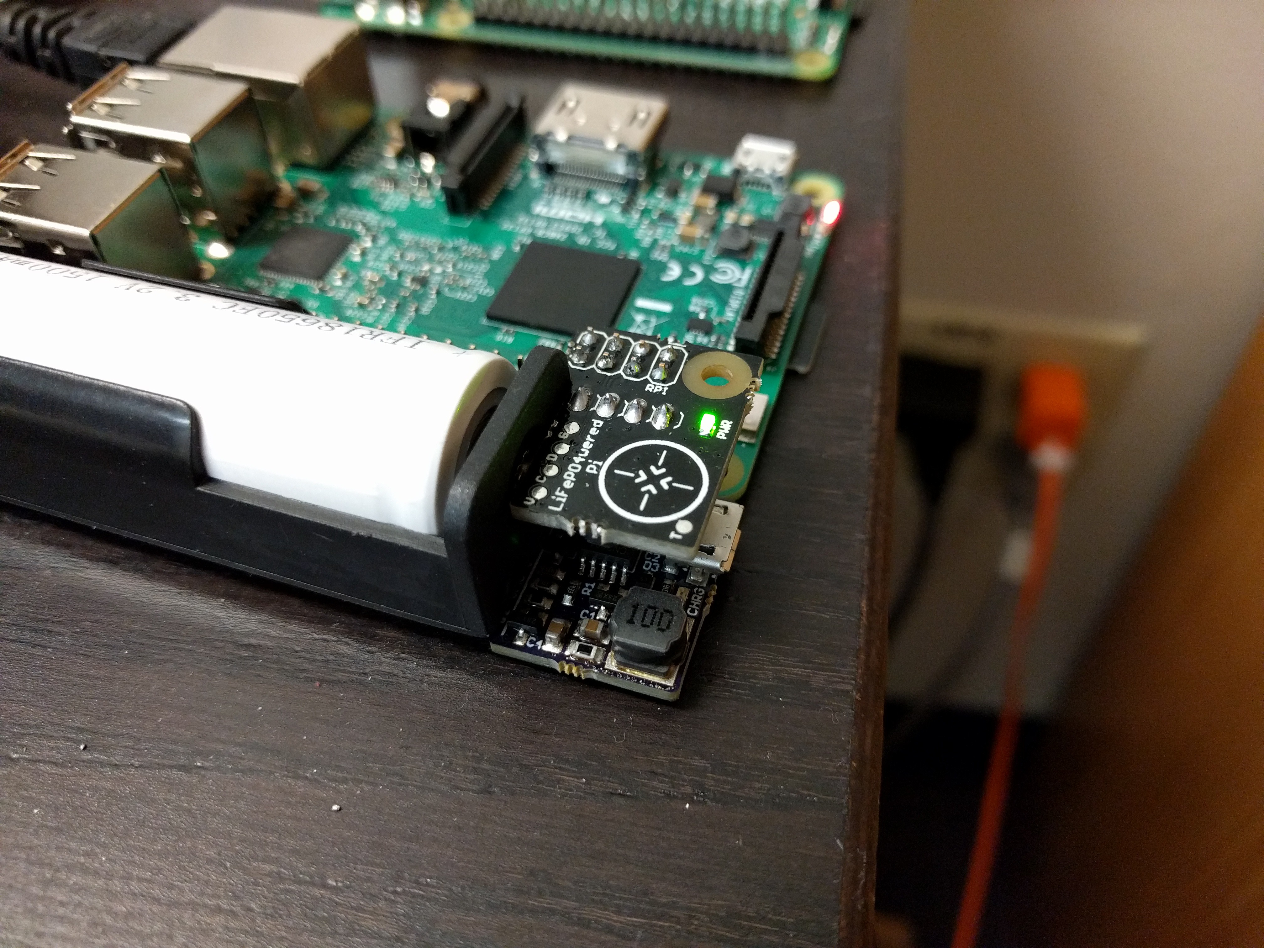
    Here is a prototype in action:

    At first glance everything is working just fine.  I didn't really test this thoroughly, but I had the feeling the circuit stayed cooler at high loads as well, which makes sense since the chip has lower RdsON MOSFET switches than the MIC2876.

    At some point during my testing I turned the Pi off and connected power to the Raspberry Pi's own power input.  To my great surprise, the boost converter started to become hot!  What in the world?

    A little background information may be useful here.  When I search for a boost converter for the LiFePO4wered/Pi, I always look for parts that have a bidirectional load switch.  The reason is that although there is no point to it, you can guarantee someone will plug power into the Pi at some point.  The bidirectional load switch makes sure that in such a case, no parasitic current flows from the Pi's 5V into the battery, while firmware makes sure the LiFePO4wered/Pi refuses to turn the boost converter on.

    My current production MIC2876 is such a part.  In the datasheet it specifies it has a "Bi-Directional True Load Disconnect".  So when searching for a potential replacement, I look for the same thing.  The RT4812 datasheet states it features a "True Load Disconnect".  I assumed that was their marketing term for the functionality I was looking for.  And I was wrong.  When powering the Pi from another source, the RT4812 apparently allows current to flow back into the battery.  Very disappointing, since it seems a nice part otherwise.

    At this point I can't help but wonder what "True Load Disconnect" is supposed to mean.  If it only works one way, isn't that just regular on/off functionality?  It doesn't seem necessary to even mention it, let alone call it by a fancy name.

    On the upside, the RT4812 gets warm but does seem to survive the condition just fine.  What's worse is that I measured 4.4V across the battery, 5V minus the diode drop of the MOSFET's body diode.  That's unacceptable, the maximum voltage across a LiFePO4 cell is only supposed to be 3.6V.

    So, back to the drawing board.  Since I'm running out of stock I decided to do another run with the current design, but using a slightly adjusted layout.  The new layout has a different footprint for the MIC2876.  When I first designed the board, I had used a footprint I had found somewhere in the Eagle library, and it turns out it doesn't really match what is specified in the datasheet very well.  I custom made the new footprint according to the spec and also ordered a new stencil to go along with it.  I'm hoping that this will solve some of the assembly problems I've experienced with the chip.

  • New boost converter evaluation

    Patrick Van Oosterwijck09/21/2017 at 16:52 0 comments

    Even though I'm focusing most of my new development effort on the next gen #LiFePO4wered/Pi+, that doesn't mean the LiFePO4wered/Pi shouldn't get any love!

    One thing that I've started to notice now I've sold over 750 of these things is that the part that gives me the most trouble is the MIC2876 boost converter.  It's the only part that gives any trouble really.  The tiny little DFN package seems to not always be mounted correctly on the boards I get from the CM, so I need to rework some of them and that's a pain.  Worse, I've even had some field returns where units that were working fine before shipping, would not work when they arrived at the customer, and it's always this part that's been the problem on the returns I've analysed.

    So I've been looking for a more robust replacement and I think I've found a good candidate to try: the Richtek RT4812.  It has a nice small leaded package, so assembly problems should go away, and with power MOSFETs that have 1/2 to 1/4 the RdsON as those in the MIC2876, it also should heat up less under heavy load, possibly extending the load current range.

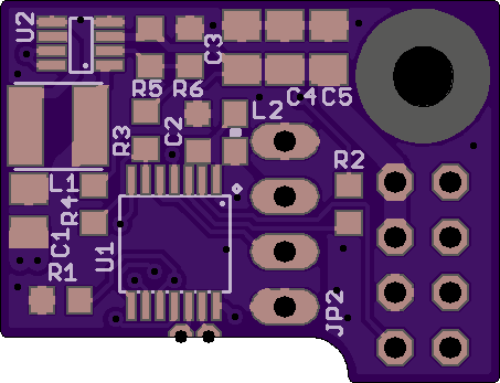
    So I've made a prototype layout to evaluate this change:

    The RT4812 runs at a lower switching frequency than the MIC2876 and specifies a larger output capacitance, plus it doesn't have a fixed output voltage version, so between the extra capacitors and resistive divider the layout has become even more dense.  But it all fits and that's what counts. :)  The design has been sent to OSH Park, I can't wait to see how it performs!

  • LiFePO4wered host software on LibreElec

    Patrick Van Oosterwijck03/30/2017 at 17:33 0 comments

    One of my customers, Raman Sarin, spent some time trying to make the host software work on LibreElec, a small Kodi distro that doesn't come with all the bells and whistles expected for compilation.

    I have not tested this myself, but here are his instructions verbatim in case someone else wants to give this a go:

    1. Get another SD Card and install Raspbian
    2. Go through the steps in the documentation to get the GIT depot onto your Raspbian install
    3. Edit the lifepo4wered-daemon.c file and change the shutdown function to this:
    
    void shutdown(void) {
      syslog(LOG_INFO, "LiFePO4wered/Pi triggered shutdown");
      char *params[6] = {"shutdown", "-h", "-t", "60", "now", NULL}; // shutdown halt in 10 seconds
      execv("/sbin/shutdown", params);
    }
    
    4. Build the files
    5. Copy the BUILD directory to a USB stick
    6. Shutdown the pi and swap to the LibreElec SD Card
    7. Boot the pi
    8. SSH into LibreElec 
    9. Copy the files from the usb to sbin directory 
    	a.  cp /media/ESD-USB/LiFePo4wered-Pi/build/DAEMON/lifepo4wered-daemon /usr/sbin/
    	b.  cp /media/ESD-USB/LiFePo4wered-Pi/build/CLI/lifepo4wered-cli /usr/sbin
    10. Make the files executable chmod u+x filenames
    11. Make sure I2c is enabled by editing config.txt file
    nano /flash/config.txt (at the end)
    
    ################################################################################
    # Adding information to turn on i2c1 for later rpis
    dtparam=i2c1=on
    dtparam=i2s=on
    
    12. nano /storage/.config/autostart.sh
    	
    	(
    	        ~/LiFePO4wered-Pi/build/DAEMON/lifepo4wered-daemon
    	)&
    	
    13. Now manually start the daemon so you can configure it
    14. Now configure it, I'm using the following, this makes sure the Pi starts up when plugged in and shutsdown cleanly when power is removed. However it also means you can't power it off in software it'll just reboot again.
    	a. lifepo4wered-cli set AUTO_SHDN_TIME 2
    	b. lifepo4wered-cli set AUTO_BOOT 3
    	c. lifepo4wered-cli set CFG_WRITE 0x46 
    15. Now reboot the Pi and start testing.

  • LiFePO4wered/Pi+ prototype

    Patrick Van Oosterwijck03/29/2017 at 22:41 0 comments

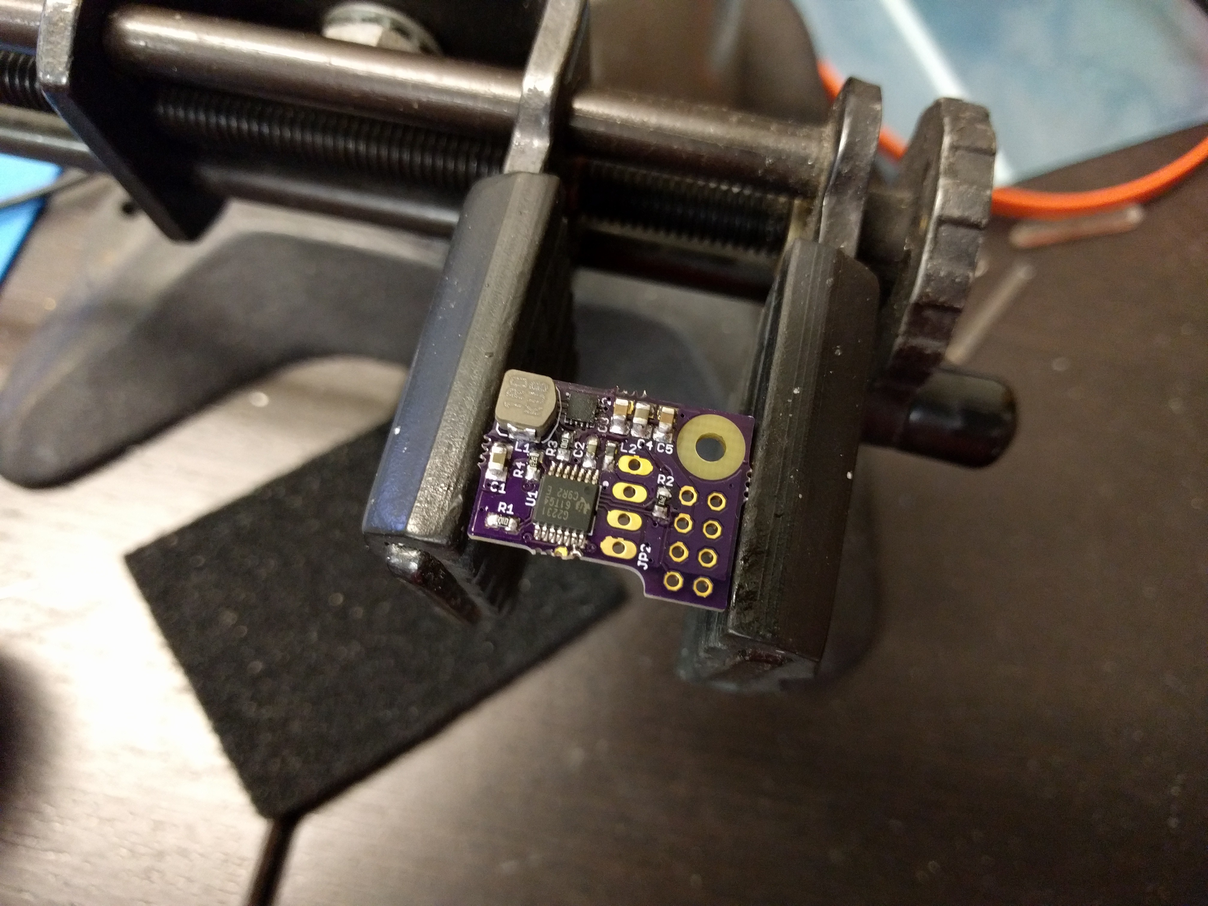
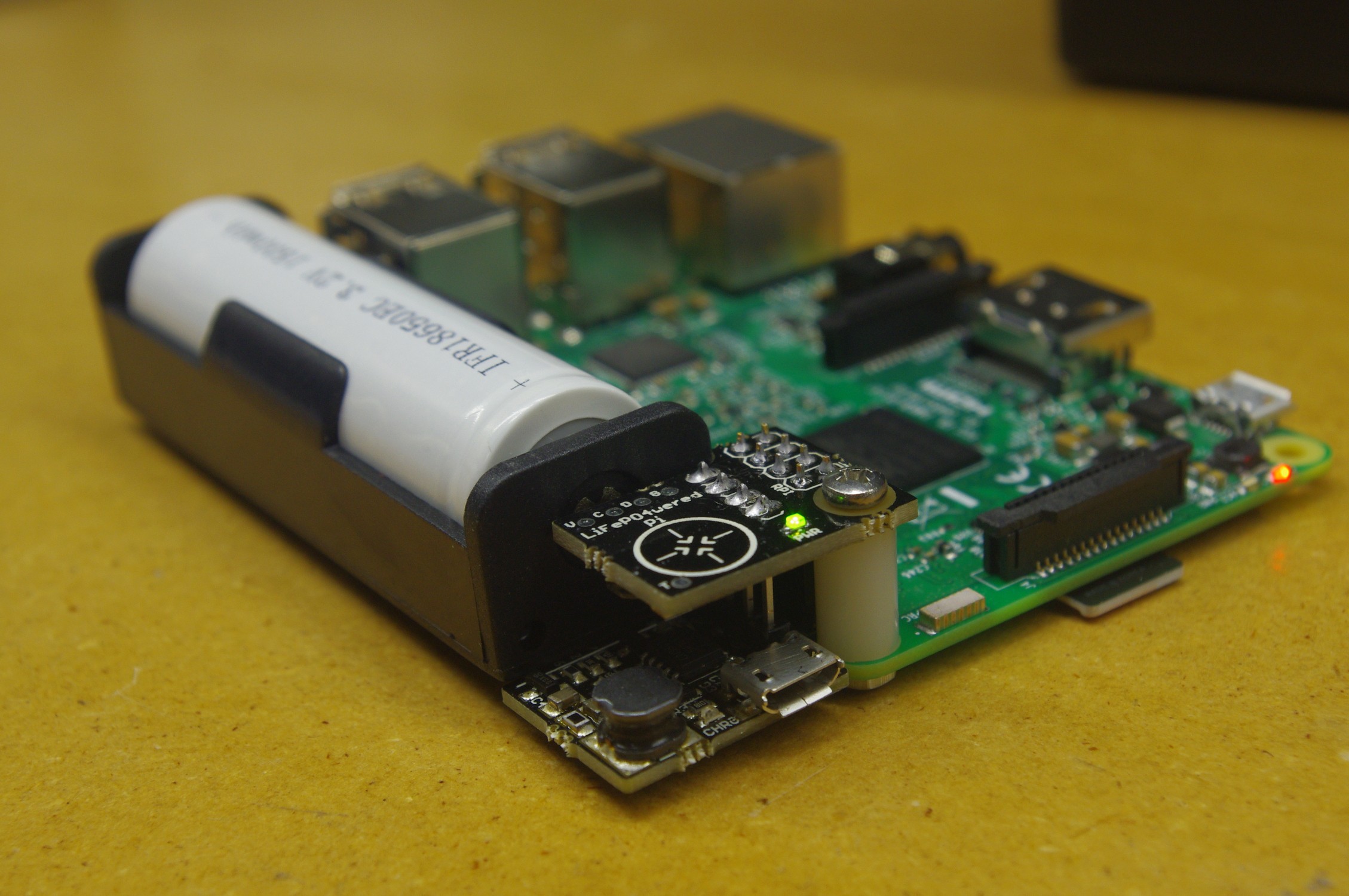
    Prototype PCBs for the higher power LiFePO4wered/Pi+ arrived from OSH Park, so I built up a prototype:

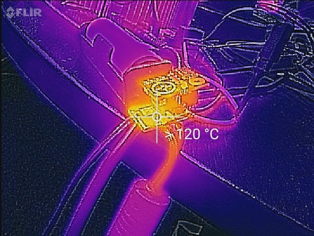
    I also hacked a #LiFePO4wered/18650 to charge at up to 3A instead of 1.3A as a base for this. This proved to be a bit of a challenge. The charger uses an asynchronous buck converter topology, and the little Schottky diode kept getting too hot and burning out. So I had to hack in a diode in a big SOD-128 package to make it work. It's still getting too hot but it's surviving so I can do the testing with this power manager. This is a basic problem with asynchronous converters: you can never get rid of the voltage drop over the Schottky diode, and at high currents, it becomes a power dissipation problem.

    The thermal image below shows the charger getting "too hot" when charging at 3A:

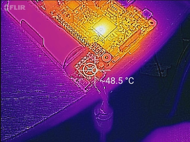
    The new TPS61235P boost converter is pretty amazing though. With the Raspberry Pi3 running with 4 cores at 100%, the CPU at > 100C, the boost converter is hardly breaking a sweat:

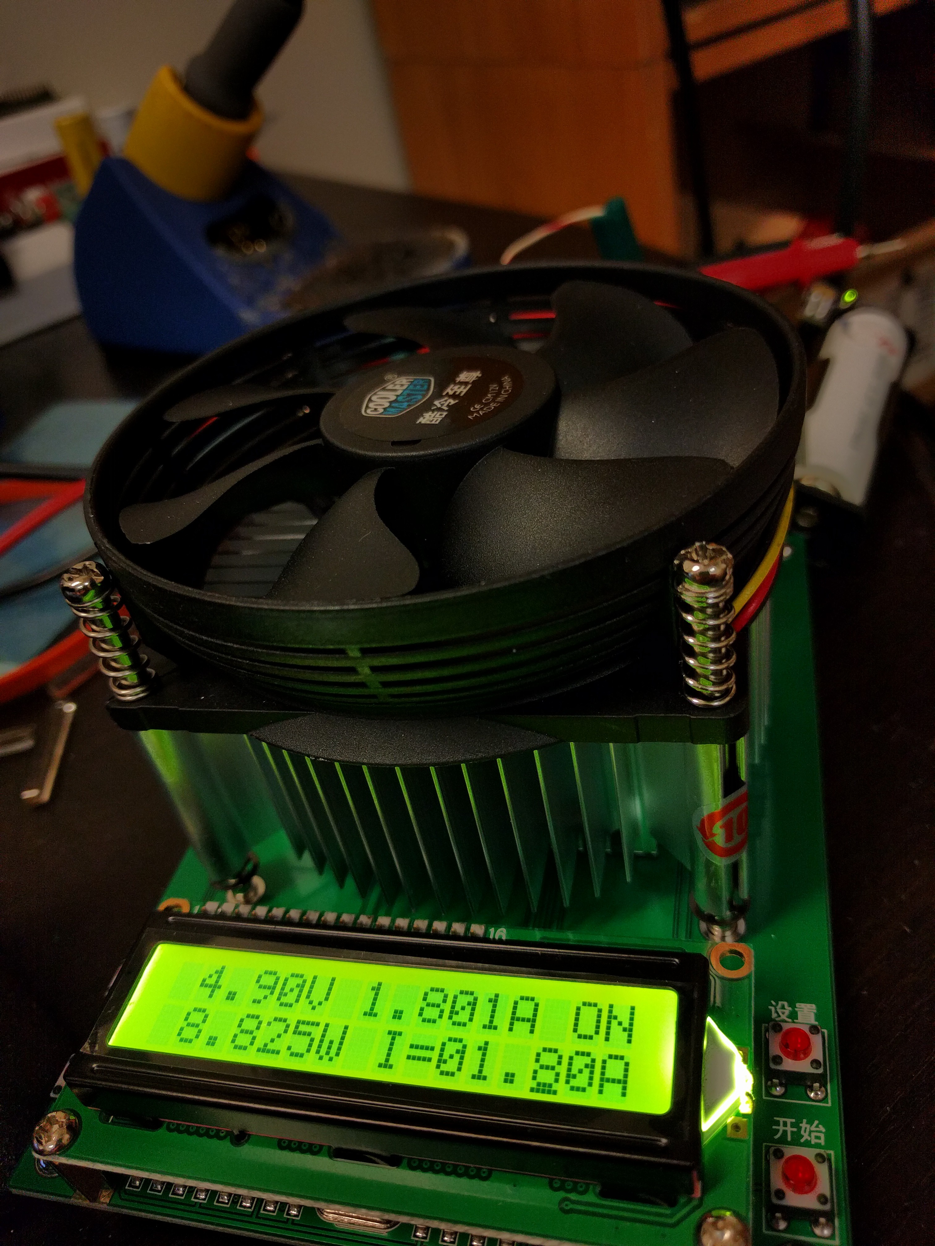
    Very nice! So time to put it on the electronic load and see how high it can go:

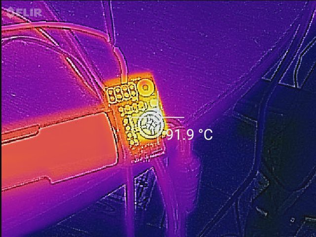
    And here is a thermal shot at this load current:

    I have to admit that eventually, the chip did a thermal shutdown at 1.8A. I lowered the load to 1.6A and it's been running for several days now (while charging, which provides a ton of heat on its own).

    Overall I'm very happy with this result. It's capable of providing twice the power of the current LiFePO4wered/Pi before going into thermal shutdown. The components were chosen to provide up to 3A, but I think I have to face the reality that in this form-factor, that is not going to happen. The PCB is just too small to provide any substantial heat sinking. If I want to get to 3A, I will have to change the design and go to a larger PCB.

    The #LiFePO4wered/18650 charger may actually be more of a limiting factor to get to 3A though. It's doing it in this prototype, but not at a healthy, mass producible temperature. I may need to look into a synchronous switching solution to get rid of the inherent voltage drop of the diode, which would always result in ~1.5W of power dissipation at 3A.

    In the meantime, this still provides a path to an improved LiFePO4wered/Pi3. 1.7A is a huge improvement over 0.85A. And even though 3A charge current seems to be out of reach for the #LiFePO4wered/18650, 1.8A may be a whole lot more manageable.

  • Power ping-pong

    Patrick Van Oosterwijck03/22/2017 at 20:22 0 comments

    It's funny how this project has evolved over time. It started with the #LiFePO4wered/USB, which I once connected to a Raspberry Pi as a demo for a Mini Maker Faire. It seemed to work well, and out of that the LiFePO4wered/Pi was born.

    Then people wanted to use the LiFePO4wered/Pi as a UPS for the Pi 3, which drew more power than the #LiFePO4wered/USB charger could support, so I created the #LiFePO4wered/18650 as a more powerful charger and the LiFePO4were/Pi3 was born.

    Now people are trying to power complete systems including hard drives and LCD screens from the LiFePO4wered/Pi3 and turns out it still isn't powerful enough. It seems the power craved by makers is insatiable. :)

    I have received reports of customers powering Pi 3s with LCD screens successfully, and others reported that this failed. The worst thing was that according to the reports the LiFePO4wered/Pi3 did not do a clean shutdown first but power just went away, indicating the boost converter went into thermal overload and switched off. I decided that instead of calibrating this with "it can power a Pi3 at 100% CPU", I needed to come up with some real numbers. So I got a nice electronic load from AliExpress and did some testing:

    Testing indicates that the maximum continuous load that doesn't cause the boost converter to go into thermal shutdown, at room temperature and with no extra cooling, is around 0.9A. The system had been designed with components rated for 2A, but on the tiny PCB it seems the boost converter just can't dump enough heat. Keep in mind that this is a thermal effect, so it takes time for the temperature to build up, meaning peak currents of 2A may be fine but are not sustainable over time.

    The LiFePO4wered/Pi was originally designed for a Pi Zero or Model A+ or B+ load, for which it works fine. Then the "ping" of making the charger more powerful made the LiFePO4wered/Pi3 possible, still using the same boost converter. But now people want to power all kinds of peripherals as well, and a "pong" to bump up the current capability of the boost converter may be in order.

    Luckily new and improved components arrive on the market all the time, allowing more powerful circuits in even smaller dimensions. One such component is the TI TPC61235P, which is a significant step-up to the MIC2876 I currently use. So I made a new layout based on this component and have prototype boards on order from OSH Park:

    Tight, but it all fit. Can't wait to test performance of these prototypes!

  • LiFePO4wered/Pi3 released!

    Patrick Van Oosterwijck12/20/2016 at 20:47 9 comments

    Kind of late I know, people following me on Twitter or looking on Tindie already knew. I had forgotten that I hadn't mentioned it here yet, sorry. :)

    So you can now buy a close-to-perfect power manager for the Raspberry Pi on Tindie! I wouldn't have dared to make such a claim about the LiFePO4wered/Pi, there were too many people who wanted to use it with the Pi 3 and who wanted input voltage monitoring and the behavior associated with that. But now that both these cases are supported with the LiFePO4wered/Pi3, we're getting there! :)

    A couple of things are still missing:

    • Adding RTC functionality would be great.
    • Some people don't need a big battery for long run times. They just want a small battery to shut down safely, but be able to run indefinitely at high load when plugged in. While the LiFePO4wered/Pi3 can be used for this, its battery is overkill. So... I have some ideas. :)

    If you like this and want to support my continuing development, please had over to Tindie and buy one!

  • Load tests LiFePO4wered/Pi3

    Patrick Van Oosterwijck12/13/2016 at 23:24 0 comments

    I did a couple more load tests with the LiFePO4wered/Pi3, the variant that uses the #LiFePO4wered/18650 as a charging base (and should be for sale very soon now). A lot of people seem to have applications where they want to use a Pi 3, use the LiFePO4wered/Pi as UPS, and also plug in a USB flash drive. Since flash drives are power hogs, I decided I should test some scenarios with a flash drive plugged in. So here are a couple of tests I did, with the LiFePO4wered/Pi3 charging from a 2A USB charger:

    • Pi 3, 4 cores @ 100%, ssh connection with a WiFi USB dongle (the built-in WiFi on my Pi 3 died), USB flash drive plugged in: slowly discharges (the system consumes more than the 1.33 A charge current).
    • Pi 3, 3 cores @ 100%, ssh connection with a WiFi USB dongle, USB flash drive plugged in: charges!
    • Pi 3, 4 cores @ 100%, ssh connection over Ethernet, USB flash drive plugged in: charges! :)

    I'm quite happy with these results. Systems running at 100% CPU continuously are very unusual. Using a WiFi USB dongle on a Pi 3 is very unlikely as well (unless breaking that silly flip chip without any protective packaging is common, which wouldn't be too surprising). I'm certain the on-board WiFi uses less power than a WiFi USB dongle, so I'm pretty confident that scenario with the CPU @ 100% will work as well. I really should get myself another Pi 3 some time so I can test it.

  • Firmware work

    Patrick Van Oosterwijck12/02/2016 at 21:14 0 comments

    I've been doing a lot of work on the LiFePO4wered/Pi firmware this week. Much of that was related to new functionality made possible by the ability to measure the input (USB) voltage with the new #LiFePO4wered/18650 base, but the quality time I spent with the code also resulted in some good improvements across the board, including for the standard LiFePO4wered/Pi. Here's a summary:

    • Auto boot when plugged in. Aside of the old "always boot when there's enough battery voltage" auto boot, being able to measure the USB input voltage enables the addition of an "always boot when there's enough input voltage and the USB power is present" function that so many people want.
    • Smart auto boot. It's fine and dandy to automatically boot when power returns, but it's kind of annoying if this prevents you from shutting the Pi down on purpose. Based on a suggestion from a user, I added smarts so that the auto boot only occurs if the system was shut down due to a low voltage condition, not when the user did a shutdown either with the touch button or from a program on the Pi. This is now an option for both the battery voltage based auto boot and the USB voltage based auto boot if it's available.
    • Auto shut down with timer. Many people want the Pi to cleanly shut down when external power goes away and boot up again when power comes back. This is now possible by combining the auto boot and auto shut down features (only with the new #LiFePO4wered/18650 base). The auto shut down will shut down the Pi if external power has been gone for a settable number of minutes. It is actually always active, but by default it's set to 65535 minutes and the battery won't last that long, so the feature is effectively disabled. :) If you want the Pi to immediately shut down when power goes away, set the auto shutdown time to 0. If you want the Pi to keep running across power outages up to 20 minutes, set it to 20. If the outage is longer than 20 minutes the Pi will be shut down with plenty of battery power left.
    • Improved wake timer accuracy. While implementing the auto shutdown timer, I implemented a new minute timer subsystem that's much better than the one I had for the wake timer. So now the wake timer also uses this new minute timer and benefits from much more accurate timing. It still uses the micro's internal RC oscillator, but it's much less dependent on variation due to other stuff going on in the code. As an example, I just ran a test of the auto shut down feature with the time set to 30 minutes, and it triggered a shutdown at 29:59. Nice! :)

    The improvements that are dependent on measuring the USB input voltage will be available when the version with #LiFePO4wered/18650 base goes on sale, the other improvements will be in every LiFePO4wered/Pi unit going forward!

  • Pi 3 testing with 18650 battery

    Patrick Van Oosterwijck11/24/2016 at 00:57 0 comments

    I'm making good progress on the new #LiFePO4wered/18650 base for Pi 3 versions of the LiFePO4wered/Pi, see this project log.

    Meanwhile I've been doing some stress testing on my first prototypes. I've been running a Pi 3 at 100% CPU for 5 days straight, powered from the prototype (plugged in of course), covered with a box to contain as much heat as possible, and it's been rock solid. Yay! :)

    So now that I have a new prototype that is pretty much identical to what I intend to run in production, I'm going to do the same test with it:

    First I'm having the battery run out, then I'll let the system charge while under high load for a week or so and see if everything behaves well. If it does, I'll go ahead and order production panels.

View all 48 project logs

Enjoy this project?

Share

Discussions

Jacob Killelea wrote 04/25/2023 at 05:21 point

Hey there, I've been following this project a little and I really like the end result! I wanted to ask whether your considered a design that would just piggyback off of the 5V rail on the Pi and kick in to provide power when the primary power is lost? Every battery backup system I see uses a separate charging port.

  Are you sure? yes | no

Patrick Van Oosterwijck wrote 04/25/2023 at 15:39 point

In my case (especially for the newer #LiFePO4wered/Pi+) one reason for the separate charging port is that it supports solar charging and high input voltages (up to 24V for the LiFePO4wered/Pi+).  But in general, if you power the Pi through the 5V GPIO connection and also use this as charging input, you get some weird "circular power" issues.  You have to manage things carefully to make sure that you charge only from incoming power and not from your own 5V you're putting on the rail.  I think it's possible to make it work with careful sensing of the direction of current, and I've started design work in that direction several times, but not finished anything.

  Are you sure? yes | no

Jacob Killelea wrote 04/25/2023 at 18:22 point

Gotcha. I think two load switches and a current sense resistor could solve this in an interesting way. It's something I've been considering trying.

  Are you sure? yes | no

Arnaud Petitjean wrote 06/07/2018 at 08:23 point

Hi there! Is LiFePO4wered/Pi3 compatible with the latest release of the Rapberry Pi3 B+?

  Are you sure? yes | no

Patrick Van Oosterwijck wrote 06/30/2018 at 16:33 point

Not entirely, it may not be able to support UPS functionality for the B+ if it is under continuous full load.  The LiFePO4wered/Pi3 is superseded by the #LiFePO4wered/Pi+, which _is_ fully compatible with the B+ under full load!

  Are you sure? yes | no

jonb42 wrote 11/21/2017 at 01:33 point

I'm wondering if using this product will interfere with using 1-wire devices? I have a raspberry running myScada (http://www.smarthouse.cloud/) and reading temperature from various 1-wire sensors using pin #7 (GPIO 4). This device purports to use pin #7 as well so I wanted to make sure there won't be a conflict... thanks! - Jon

  Are you sure? yes | no

Patrick Van Oosterwijck wrote 01/07/2018 at 18:18 point

Hello Jon,

Pin 7 isn't actually connected to anything on my device, so it should work fine. :)

  Are you sure? yes | no

Boris wrote 10/23/2017 at 23:24 point

Hi Patrick, 

I purchased the 600mAh version of the device. I would like to use it at close to +5 deg C, and would like to solder 5V input wire directly. What would be the best way to solder 5V in?
Also, is there a Python module or wrapper for the CLI? (I'm hesitant to use subprocess)
Thank you.

  Are you sure? yes | no

Patrick Van Oosterwijck wrote 01/07/2018 at 18:16 point

Sorry about the late reply Boris, I hadn't check this page for a while.  The 600mAh version unfortunately doesn't include any solder pads for input voltage like the 18650 version does.  Using the micro USB is the only good option really.

On the other question, I'm happy to say there is now an official Python and Node.js wrapper available in the host software repo!  Let me know if there's any issues you run into, since this is a pretty new development.  Be sure to recompile and reinstall the host software as the wrappers use the shared object and they need to be in sync.

  Are you sure? yes | no

jonb42 wrote 10/03/2017 at 19:11 point

I bought a few of these sight unseen and am so far very impressed. I love the LED feedback and touch button and ease of installation. 

I do have a feature request for the future: make the mounting system a bit more robust. Right now it mounts via one standoff and bolt, and it really needs another support at the other end.

Also I can see wanting to use this in another case - in my case (!) this would be the case that mounts the 7" touchscreen display. There isn't room in this for a device that sits BESIDE the Pi - it needs to mount ABOVE, perhaps on a stackable shield of its own - or perhaps just sell some lengths of ribbon cable with 8-pin connectors so that it can easily be mounted outside an existing "standard" case.

  Are you sure? yes | no

Patrick Van Oosterwijck wrote 01/07/2018 at 18:12 point

The mounting system indeed could be improved, that's why I'm designing the next gen #LiFePO4wered/Pi+ in such a way that it can be mounted with at least 2 screws. It also will make it easier to attach custom 3.2V LiFePO4 packs so you can have the pack wherever you want.

  Are you sure? yes | no

Sam Kang wrote 09/19/2017 at 13:32 point

Hi Patrick, I am surprised that this little thing can do all it does without taking up so much space. I've seen other PI UPS projects and most had many more passives and chips on them. I like your project and fully support it. 

Hope you remember me. I am the one having trouble with compatibility with 3G HAT. 

It would be great to get a firmware update to allow LiFePO4wered/Pi3 to shutdown even with other HATs pulling UART TX pin high.

  Are you sure? yes | no

Patrick Van Oosterwijck wrote 09/20/2017 at 14:35 point

Thanks Sam!  I do sometimes wonder what the other UPSes need all that stuff for. XD  Chalk the small size up to my obsession to make everything tiny, and the use of 2 PCBs stacked.

Mine is growing a bit in the next generation #LiFePO4wered/Pi+ as well though, mostly to ease manufacturing, provide larger current and provide more hacker friendly connectivity.

The firmware update you mention is stuff on my to-do list, which is waaay too long unfortunately.  Shouldn't be too long now, stay tuned!

  Are you sure? yes | no

Colin Ng wrote 07/02/2017 at 19:56 point

Hi Patrick, I like the design of the LiFePO4wered/Pi3!

I was wondering if it could be modified to reduce the header height. I'd like to use it with the HealthyPi v3 in a semi-permanent installation:

https://www.crowdsupply.com/protocentral/healthypi-v3

They suggest a Battery Hat but that makes for a very tall stack:

https://www.crowdsupply.com/protocentral/healthypi-v3/updates/healthypi-v3-with-raspberry-pi-3-pi-zero-as-a-wireless-standalone-monitor


Would it be possible to shorten the distance between the 18650 board and the UPS board, and solder the UPS board directly onto the GPIO header near the base, and then stack the HealthyPi v3 board on top?

How close can the 18650 board and the UPS board get? With the anticipated low power draw of the HealthyPi v3 would omitting the heat sink on the charge circuitry be okay? 

I was thinking of shortening a LiFePO4wered/Pi3, soldering that to the base of a GPIO Hammer Header, hammer that into a Pi Zero W and stack the HealthyPi on top. If the Pi Zero W dies I'd hammer the header back out. 
https://shop.pimoroni.com/products/gpio-hammer-header

Just curious what your thoughts are - please overlook my obsession about all things diminutive.  :)

  Are you sure? yes | no

Patrick Van Oosterwijck wrote 07/03/2017 at 17:09 point

Hello Colin,

Due to the inductor, the closest the two boards can be is ~6mm.  I don't know if that's close enough for your application?  The LiFePO4wered/Pi3 would likely hang down a couple of mm below the Pi.

I would suggest another possibility.  If you have a LiFePO4wered/Pi3 without the 8-pin header installed, you might be able to permanently solder the header connections to the top side of the HealthyPi header.

If you want to try either approach, just mention in the comments on your Tindie order that you don't want the header installed, and whether you want the PCBs as close as possible.

BTW Just look at my stuff and I think you can tell I have an obsession with diminutive as well. ;)

  Are you sure? yes | no

Colin Ng wrote 07/03/2017 at 23:18 point

Hi Patrick, 

I ordered a LiFePo4wered/Pi3 and requested it without the 8 pin header, and also without the 2 boards soldered together so I can find longer pins and have the UPS board soldered atop the HealthyPi v3 as suggested. 

I'm going to ask if they can provide my HealthyPi v 3 without the 40 pin header, so that I can I use a female Hammer Header whose pins are longer, hopefully resulting in stronger solder joints. 

Thanks for the suggestions! 

Colin

  Are you sure? yes | no

Patrick Van Oosterwijck wrote 07/05/2017 at 22:15 point

Hello Colin,

That sounds like a plan.  I shipped your order in pieces without the 8-pin header and included the connecting header I use in case it's long enough if you don't make it go through the holes very far!

  Are you sure? yes | no

Walter E. Gunter, Jr. wrote 02/28/2017 at 02:04 point

so, dumb question... I just got mine today and plugged it in, loaded the software and can see voltage and have tested the auto boot function.  LOVE IT!!! I would like to put something like the little icons in the toolbar for ethernet and cpu to monitor voltage, but that's another topic.  If this battery is only 3.2V, but the pi3 needs 5V and almost 2Amps, can you explain a bit.  

My plan is to power a portable pi solution for my kids.   So, there will be a screen, but that's about it since i will use the pi3 bluetooth and wifi/ethernet running raspbian/pixel.   Typically, I would like a 3-5 hour play time without being connected to power.   Thoughts?

  Are you sure? yes | no

Patrick Van Oosterwijck wrote 03/03/2017 at 20:12 point

The circuit has a booster that brings the 3.2V up to the 5V used by the Pi.  It is a limiting factor and cannot provide 2A continuously due to thermal shutdown of the booster on the tiny board.  It might not be able to provide enough power for the screen.

  Are you sure? yes | no

Walter E. Gunter, Jr. wrote 03/06/2017 at 02:25 point

I have successfully been using it with the PiTft Capacitive https://www.adafruit.com/product/2423 , no shutdowns. no low power icons...  I am not sure what to do to get it to worst case scenario. I have launched wolfram alpha, browser, minecraft, etc.   Nothing seems to kill it  (ie, i haven't seen it shutdown or die due to too much power draw).  I have some plans for this to be a touch screen interface for a few things and love the .  I didn't realize the power of the 18650. I actually have two of them from a local make supplier here in Salt Lake City, UT.    I will use them with a power boost, but they don't have the UPS type software you have created with this.   
Alternate thought: I am having issues with fully powering off.  If I press the power button, it powers off, but the red led is still on, and i can't turn it on (ie, i get the fast blinks since it cannot take another command).   Thoughts?

  Are you sure? yes | no

Patrick Van Oosterwijck wrote 03/06/2017 at 20:26 point

Walter,

Nice to hear it's working for your setup with a touch screen!  The fact of the matter is that there's no way for me to test as many different configurations as my customers can, so it's always nice to hear what works and what doesn't.

As for your LED question, it's normal for the red LED to stay on a while after you turn the system off.  It indicates charge status, which is separate from the power manager.  Even if the battery is mostly charged, once the load is gone, the charge controller will top off the battery until it reaches charge termination.  Then the red LED will go off.

Not sure why it would refuse to turn back on though.  The fast blinks would indicate the Pi is either externally powered, or the battery voltage is too low to start.  Maybe the Pi + LCD takes enough power to make the battery drain even when it's plugged in?  It's possible you turned it off in the hysteresis area between where a shutdown is forced and when boot is allowed.

  Are you sure? yes | no

ActualDragon wrote 02/02/2017 at 18:48 point

if you have such a problem with it, build your own. that's why ur an engineer. get out and try it yourself instead of #failing it. personally i think it's a little expensive, but i understand the whole business part. just don't buy it

  Are you sure? yes | no

[deleted]

[this comment has been deleted]

davedarko wrote 02/05/2017 at 17:16 point

Seems like they're simply analysing your comment as rude behaviour, too ;) No engineering flaws were pointed out buy you, only financial decisions you probably have never had to make. Sure, It's probably cheaper to order all the parts he mentioned and design a little board around them for yourself. But selling is a whole different story, you want to take money for your work time as well and have some margin for faulty boards and all that. Hope that helps to understand the pricing :)

  Are you sure? yes | no

davedarko wrote 02/05/2017 at 17:32 point

Those who are selling shields/hats for the PI not responsible for the pricing of the Raspberry PI itself and I'm sure they're still selling some shields that it makes sense for them, even knowing that those can easily double the price of the system. So I don't think it's fair to come here and 'spit' your thoughts on a very well documented project and tell that it's overpriced and "over-documented" :D 

  Are you sure? yes | no

[deleted]

[this comment has been deleted]

Patrick Van Oosterwijck wrote 02/01/2017 at 22:46 point

Eh?  Of course it costs more than a Pi.  Everything does.  If you're an engineer you should know why.

  Are you sure? yes | no

EngineerAllen wrote 02/01/2017 at 23:01 point

the components & pcb have almost no cost even in low quantities (from china)

how much are you being charged to get them populated?

i havent made products just do my own soldering

  Are you sure? yes | no

Patrick Van Oosterwijck wrote 02/02/2017 at 00:06 point

Then I suggest you make a product and try to build a business around it before you go around declaring other people's hard work to be #fail.  There's much more involved than component cost and soldering.

  Are you sure? yes | no

Patrick Van Oosterwijck wrote 02/05/2017 at 17:57 point

Seriously, go troll elsewhere.  This project has been well received beyond my wildest dreams.  I'm very happy most people understand the concept of overhead, and the only place it seems to have failed is in your head.

If you're here to analyse engineering ability then I'll save you some time and let you know right now that I'll never do business with you.

  Are you sure? yes | no

ajlitt wrote 02/02/2017 at 18:14 point

Low volume hardware manufacturing is expensive, especially if you're in the U.S.

Also protip: don't troll from an account with your linkedin page linked at the top of your profile.

  Are you sure? yes | no

davedarko wrote 02/05/2017 at 17:27 point

@EngineerAllen - I don't see any reason to call people names, would you please keep it nice? this is not the comment section of the hackaday blog.

  Are you sure? yes | no

EngineerAllen wrote 02/05/2017 at 17:44 point

@davedarko youre pointing the blame at the wrong person

  Are you sure? yes | no

f.hillhouse.jr wrote 01/23/2017 at 22:05 point

Greetings! I am looking at the final product and am curious about the overall interface to the RPi. I see that I2C is used. I also see that
the product connects to one of the UART pins (UART_TXD). Does the product use the serial port or GPIO? If GPIO, can this be moved to another pin? I am working with a Zero and am using the UART already. Also I assume I can still use the I2C for additional hardware (e.g., display).

Thanks and best regards!

  Are you sure? yes | no

nrrdzilla wrote 01/24/2017 at 22:37 point

I'm also interested in this. As someone just getting into using RPis; I'm not sure what the implications are.

Specifically I'd like to know if we can just cut the trace and flywire to another GPIO, like maybe GPIO4, since we already have that signal (unused) in the header? Is there anything (except for software changes) that would prevent this?

  Are you sure? yes | no

Patrick Van Oosterwijck wrote 01/30/2017 at 15:58 point

You can actually still use the UART_TXD in your project!  All it is used for in the LiFePO4wered/Pi is to detect that shutdown has happened, so it knows the power can be turned off.  This is only monitored in the shutdown state.

All communication between the Raspberry Pi and LiFePO4wered/Pi goes over the I2C bus.  As long as the software that uses any other I2C devices on the bus is well-behaved (doesn't hog the bus but uses short open/communicate/close sequences), there should be no problem using them together with the LiFePO4wered/Pi.

I sell a variant that uses a long-tail 40-pin connector instead of the small 8-pin connector, this can be used when you want to stack other HATs.

  Are you sure? yes | no

jason wrote 12/27/2016 at 23:50 point

I want to connect this to an existing project that is using pin2 (5v) to power something.  Is there a recommended place to solder a wire beyond the backside of that connector?

  Are you sure? yes | no

Patrick Van Oosterwijck wrote 12/28/2016 at 01:21 point

No, I think the backside of the 8-pin connector is the easiest place I can think of.  Other than that, the output capacitor is another spot that can be reached, even though it's on the bottom (between the 2 PCBs).

  Are you sure? yes | no

Mikey wrote 11/28/2016 at 19:37 point

Are you planning on releasing it with the option for a JST battery connector? -- I'd like to use it with one of the bigger Adafruit 6600 mAh batteries to make a portable handheld game (RetroPI, etc.). -- Also, is this compatible with 3.7v / 4.2v batteries, or only 3.6v / 4.1v?

  Are you sure? yes | no

Patrick Van Oosterwijck wrote 11/28/2016 at 19:45 point
No plans for a JST connector version, no.  Partly to prevent the scenario you just described. :)

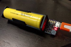
Anything with a JST connector is usually a regular LiPo, which would likely blow this up.  It's only made to work with a LiFePO4 which has a 2.7-3.6V range during the whole charge/discharge cycle.

I'm having one in the works with a 1500 mAh LiFePO4 (see #LiFePO4wered/18650), and nothing prevents you from putting more LiFePO4 cells in parallel.  Some customers have ordered without the battery and hooked up their own large cells, and this is fine as long as they're LiFePO4.

  Are you sure? yes | no

[deleted]

[this comment has been deleted]

Patrick Van Oosterwijck wrote 11/25/2016 at 18:59 point

Thank you for the feedback! :)

  Are you sure? yes | no

ColdSilver wrote 11/24/2016 at 07:42 point

The Knock-Knock & Unlock is a security system product that is based on the knocks combination you choose and/or the voice command you say to make a code for securing your things safe. (i.e house, jewels, etc.) This system provides a voice tour guide that explains how this system works, what it does and guides you how to make and define your own unique password. The product is in advanced stages of the process and in these times the search for an investor is essential.Now we are small but "Great Things Start in Small" and therefore we look forward for your support.

  Are you sure? yes | no

kaislahattu wrote 10/25/2016 at 21:11 point

Could this be used with considerably larger cell capacity? (without the battery holder and with "duct tape", accepting really long charge times)

  Are you sure? yes | no

Patrick Van Oosterwijck wrote 10/25/2016 at 22:23 point

Yes you could, in fact one of my customers ordered the top PCB (power manager) without the bottom PCB (charger + battery) and connected his own battery system.  You can contact me on Tindie for such custom requests.

  Are you sure? yes | no

Alexander von Gluck IV wrote 10/15/2016 at 00:53 point

How do you turn it off when a Pi isn't attached?  Pressing and holding the button just results in a rapid blink, then back to fade.

  Are you sure? yes | no

Patrick Van Oosterwijck wrote 10/15/2016 at 01:46 point

The LiFePO4wered/Pi isn't really made to work on its own, only in tandem with a Raspberry Pi.  When you turn it on, it's waiting for the Pi to report that it has booted and is ready to accept a shutdown command.  Only then will it accept new commands to turn off, because the Pi is able to do a proper shutdown.

When no Pi is attached, the LiFePO4wered/Pi will stay in the state waiting for the Pi to boot, which of course will never happen.  It will indicate it can't accept your command by rapidly blinking the LED when you touch the button.

If you happen to turn it on with no Pi attached, the best thing to do is momentarily disconnect the battery.

  Are you sure? yes | no

Anthony Webb wrote 10/10/2016 at 21:33 point

I just bought one, excited to kick the tires.  Only downside I see here is there are not a lot of case options (outside of the acrylic one which is not great).  Have you thought about or would it be possible to re-orient stuff such that more case options would work with your design?

  Are you sure? yes | no

Patrick Van Oosterwijck wrote 10/10/2016 at 21:45 point

Thanks Anthony! I'm hoping that more case options may appear as the product becomes more known.  I have to say I'm not super familiar with what's out there for Raspberry Pi cases, but I'm not sure if any orientation would work in an existing case.  A battery needs a good amount of space somewhere. :)

I'm working on a case design myself, a layered acrylic case.  If you're not a fan of acrylic cases it's probably not going to be of much help to you. :)

  Are you sure? yes | no

James Avery wrote 09/23/2016 at 10:45 point

This looks great! Mine just arrived, so I'm looking forward to trying it out!

  Are you sure? yes | no

James Fowkes wrote 09/14/2016 at 12:37 point

Have you had any issues with i2c clock stretching? It's been a problem in the past with the pi: https://www.raspberrypi.org/forums/viewtopic.php?p=146272.

  Are you sure? yes | no

Patrick Van Oosterwijck wrote 09/14/2016 at 14:40 point

I've run into this problem with a different project, and I had to reduce the Pi's I2C clock to 50 kHz to make it work because of the lack of decent clock stretching support (the slave I2C was completely implemented in software on that one).

I have not had any problems with the LiFePO4wered/Pi though.  The micro I use has a hardware peripheral for I2C (although I still had to implement more than expected in software), and it seems to respond fast enough so the Pi can use the default 100 kHz clock.

  Are you sure? yes | no

Similar Projects

Does this project spark your interest?

Become a member to follow this project and never miss any updates