As I've talked to more customers, two wishes keep popping up:
- Customers want to use the LiFePO4wered/Pi as a UPS for the Pi 3.
- Customers want to know whether USB power is present, and have an option to auto boot when it is.
So, work has started to make both of these wishes a reality. :)
For the first request, the limiting factor in making the LiFePO4wered/Pi work well as a Pi 3 UPS is not the LiFePO4wered/Pi power manager itself--it is perfectly capable of powering a heavily loaded Pi 3. The problem is the limited charge current of the #LiFePO4wered/USB charger. It is limited to ~500 mA because of limitations of the AA LiFePO4 cell and the linear charge chip that produces a lot of heat. It works well for the power requirements of the original Raspberry Pi, but not for the more recent, high powered versions.
To overcome these limitations, I have started a new project: #LiFePO4wered/18650. This is a drop-in replacement for the #LiFePO4wered/USB that is designed with a larger 18650 cell which allows higher charge currents, and a switch mode charger similar to the one I prototyped in the #LiFePO4wered/Solar1. This enables higher charge current without dissipating as much heat. I have running prototypes right now:

This project also includes features to solve the second issue: detection of VUSB. Where the center two pins of the 4-pin header connecting the LiFePO4wered/USB to the LiFePO4wered/Pi used to be the D+ and D- USB signals, D- on the #LiFePO4wered/18650 by default will have ~25% of VUSB connected to it (this can still be reverted back to D- for those who need it with a solder jumper).
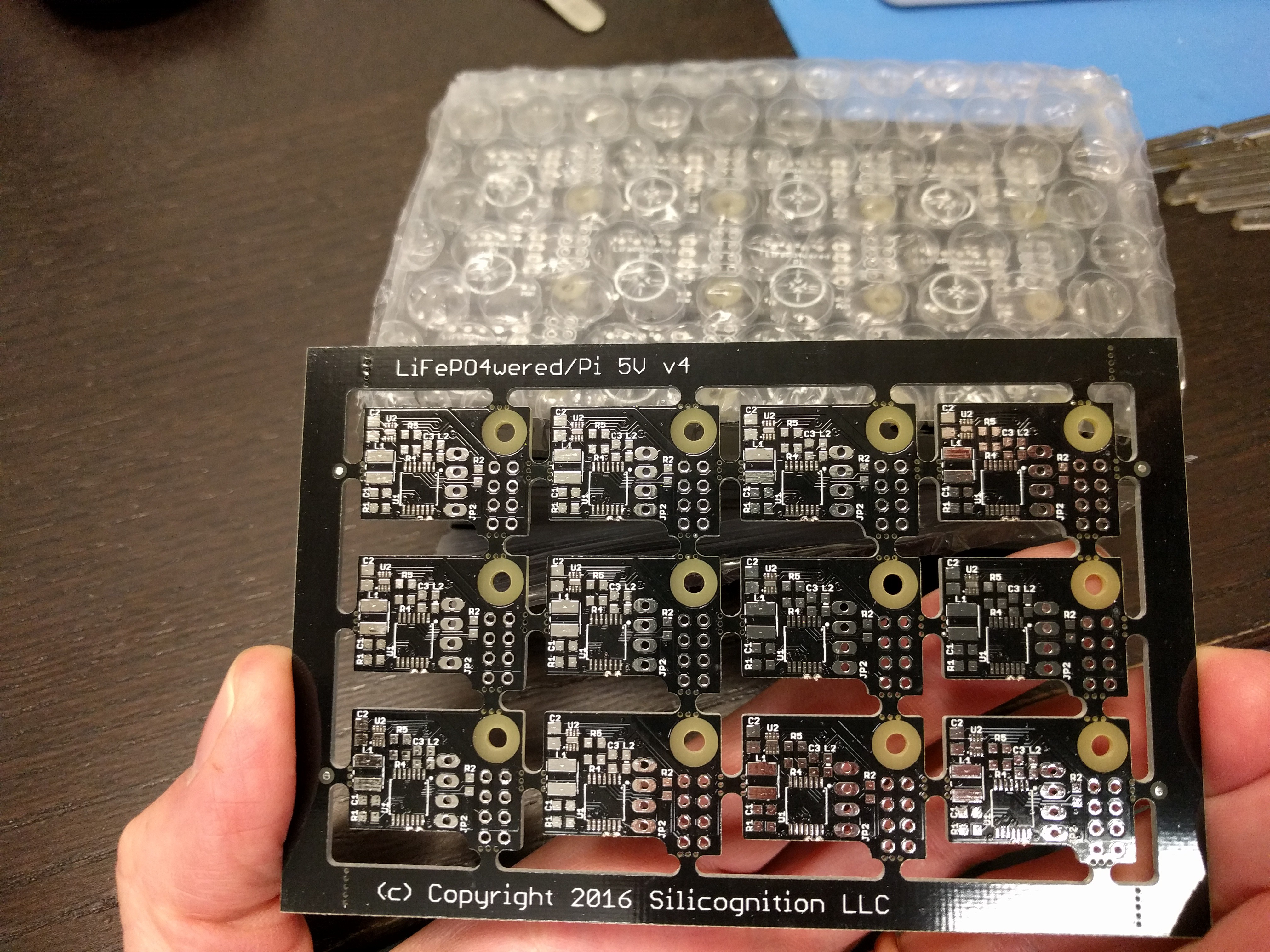
But that's only part of the solution. The current LiFePO4wered/Pi power manager doesn't connect this signal to anything. So I had to make a change there as well. Since I was running low on LiFePO4wered/Pi panels anyway, I made a tiny change and added a trace to the LiFePO4wered/Pi to connect this pin to an ADC input of the microcontroller that was conveniently available before I ordered new panels. They have now arrived:

My CM is building some new stock for me and part of the new stock will be based on these panels, so they will be ready and available by the time I'm ready to build production of the #LiFePO4wered/18650. Since the hardware at that point will be capable of detecting VUSB, it will only take a little bit of software work to make VUSB detection available! :)
This brings up another issue. When I was first writing the LiFePO4wered/Pi software, my mind was very centered on the power manager by itself. So when naming the voltages, it made sense to name the incoming (battery) voltage VIN and the output (Raspberry Pi) voltage VOUT. I realize now that this is confusing to customers who deal with the complete unit: you'd expect VIN to be the USB input voltage instead. This will only get more confusing when I will actually have the USB voltage available as well. So I have decided to rename all current references to VIN to VBAT. I will update both the host software and the documentation to reflect this.
I realize this may cause some confusion with current customers, but it seems to be the best option going forward. The longer I wait to straighten this out, the worse the problem will get. Existing customers can keep their software as is and continue to use VIN, or they can update their software with:
git pull
python build.py
sudo ./INSTALL.sh
This gets the update from Github (network required), rebuilds and then reinstalls the software to get up-to-date with the new VBAT names. I hope this won't cause too much confusion, sorry if it does! Patrick Van Oosterwijck
Discussions
Become a Hackaday.io Member
Create an account to leave a comment. Already have an account? Log In.