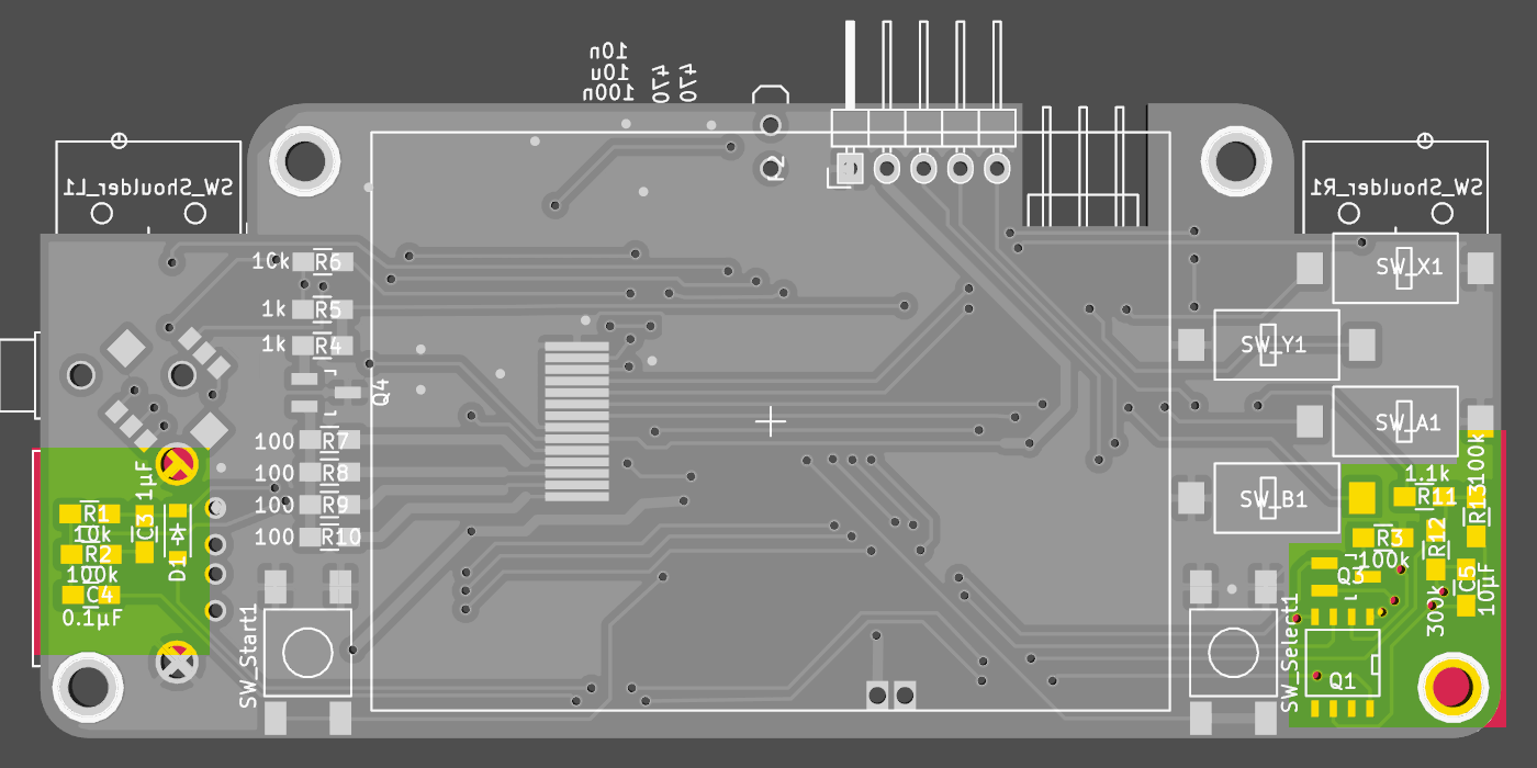
putting the components on the pcb, grouped by function - power is first


and temporarily mount the power-boost pcb (to ease removal in the worst case) - looks ugly, but gets the job done...

the two wires connect to the LiPo Battery - in the final assembly the battery will be directly soldered to those pins, since the battery jst-socket is (intentionally - was a trade-off decision...) blocked by the USB-A socket
And the next bug... ordered the wrong transistor that pulls on the enable pin of the PowerBoost... have to fix the BOM and order another one :-\
update 2016-03-10
replacement transistor arrived, turned out it didn't work as intended either :P
after some playing around with it, noticed that the pulldown (to the powerboosts enable pin) without the inversion/buffer transistor in-between just works...
since the voltage levels in the soft-power part (tow latching mosfets) are already on V_Batt level, and the connection to the raspberry is "protected" by another resistor, everything should be fine. the whole soft-power circuit was designed to turn 5V on/off, so the 3-4.2V of the lipo shouldn't hurt the pi (should, should, ...).
updated the schematics and boardlayout accordingly (see github)
 JohSchneider
Discussions
Become a Hackaday.io Member
Create an account to leave a comment. Already have an account? Log In.