-
Wireless Solar GPS Dongle Block Diagram
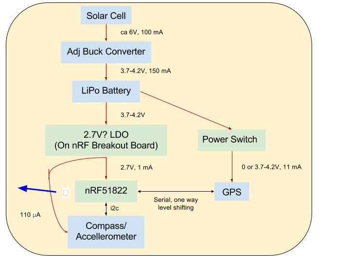
03/09/2016 at 23:47 • 0 commentsHere's a block diagram of the wireless, Bluetooth Low Energy based solar powered GPS & compass dongle:
![]()
The broken white box left of the nRF51822 should've been a Bluetooth 'B' symbol. The nRF51822 controls the power switch (A P-channel MOSFET) for the GPS power (to turn the GPS off when no one is listening). The GPS serial output voltage level will be too high for the nRF chip, so it need sto be shifted down with a voltage divider. However, the GPS should be able to read the output from the nRF chip just fine.
It would be nice to have the nRF51822 be able to read the battery voltage, but I am not sure if I'll add this. A simple voltage divider will bleed off too much current I'm afraid and drain the battery. Will need more calculations.
The compass / accellerometer board is a GY-511 board. I have not yet been able to find a schematic for it, but it's based on an ST LSM303DLHC chip.
I believe I can charge the LiPo battery safely with an adjustable buck converter like this.
I've ordered the PCBs for the nRF51822 breakout and the Raspberry Pi On/Off board. I'll update GitHub with the latest files soon.
I have all the components to start building and testing this. Until I get my own nRF 51822 breakout board, I've ordered a BLE400 to start experimenting.
I also just received the prize Pi Zero, now I'm just waiting for a micro HDMI adapter to start testing it. I'm also waiting for an SWD to JTAG adapter for the BLE400 board before I can program the nRF chip.
It seems like there is no GPS / compass service definition in BLE GATT, so I'll have to create my own. Does anyone know of one?
Since the electronics should hopefully not draw more than 13 mA while running, and the solar cell should be able to provide 150 mA in full sunlight, I should get 10 hours of runtime out of 1 hour of sunlight. A sufficiently large battery, and I should be able to manage a week without sunshine.
So much to do and so little time!
-
Woo Hoo! I'm featured on the Hackaday Blog
03/06/2016 at 21:09 • 0 commentsExtra, Extra, read all about it!
-
nRF51822-Core Prototyping Board files pushed
03/03/2016 at 20:57 • 0 commentsI just uploaded the Eagle design files for a prototyping board for the nRF51822-Core modules I'll be using as the microcontroller and Bluetooth interface for the wireless GPS dongle, and as Bluetooth module for the PiChart to a new GitHub repo. For more info, seethe project I set up for this subtask.
-
Spun off nRF51822 Core adapter board
03/02/2016 at 20:57 • 0 commentsI created a separate Hackaday project for an adapter board for nRF51822 Core Bluetooth Low Energy modules that I intend to use in both the PiChart display device and the wireless GPS & compass module.
The nRF51822 is a really nice, inexpensive (from €3.5 each for the ICs in single unit volume) very low energy chip which is both an ARM micro controller and a Bluetooth Low Energy (BLE) device.
You can buy cheap modules with the nRF51822 for under €5 on E-bay, known as nRF51822-Core. But they use 2 mm pitch connectors which are a pain, since they don't fit into breadboards.
There is a "motherboard" for these modules available, called BLE400. But it didn't fit my needs (I don't need the USB-serial chip on it, I can't choose what voltage to run it at, it doesn't have voltage shifters neccessary to work with the GPS and compass boards I bought, and it's pretty big (ca 10 x 5 cm).
So I decided to design my own adapter board that I could re-use in different projects, with footprints where I could mount additional components as I need them - LDO, voltage shifters, programming connector, reset button, LEDs, MOSFETS to turn off power to peripherals, and pads for headers so that I can connect it to a breadboard or a Raspberry Pi.
-
Won a π 0!
03/01/2016 at 12:55 • 0 commentsCool! This Project was one out of ten that won a Raspberry Pi Zero in Adafruit and Hackaday's contest.
Thanks to the judges!
-
Raspberry Pi On/Off board split to a separate project
02/26/2016 at 21:02 • 0 commentsI made a separate project, for the Raspberry Pi on/off button: see https://hackaday.io/project/9885-raspberry-pi-bake-off It's a nice minimal self-contained project.
I uploaded the Eagle schematic & PCB layout files to GitHub. I think they're ready to be sent off to be manufactured.
-
OpenGL ES code pushed to GitHub
02/22/2016 at 21:13 • 0 commentsI just pushed the OpenGL ES code to the GitHub repo. See the 'piglet' directory.
Let me know if there are any problems getting the code to build/run.
-
OpenGL ES Smooth Zooming Video
02/21/2016 at 21:48 • 0 commentsHere's a video showing the smooth zooming achieved with my OpenGL ES implementation. I also show how the Pixel Qi display turns reflective grayscale when the backlight is turned off. This should be readable in full sunlight.
I have a background thread that reads the compressed PNG tiles as required (and pre-caching tiles of higher and lower magnification). The PNG tiles are uncompressed as they are needed as textures for the map rendering.
My next steps are to fix the known bugs in the OpenGL rendering, then post the code to GitHub. Then I think I'll design the PCB for turning the Raspberry Pi on and off so that I can send the order off while I work on other things.
After that it is either getting the nRF51822 boards for the Bluetooth Low Enegy (BLE) communication from the GPS dongle to the plotter working, or starting to build the case.
-
Open GL ES Rendering
02/19/2016 at 21:58 • 0 commentsSo I guess writing the software in 300 lines of code was too easy for me ;-)
I was annoyed at the jerky response of the javascript / HTML code in the web browser under X windows. So I gave a try at writing some code in OpenGL (a first for me), thereby bypassing many layers of software and using GPU accelleration to render directly to the screen without X windows.
I now have a first rough version in about 1500 lines of C code (not checked in yet, needs some more work), that should give me buttery smooth graphics (60 Hz update) when zooming and moving.
My belief is that the SD card's speed is the main bottleneck. I use a background thread to read the compressed, palette format tile PNG images into RAM cache, and when I need to draw them as textures with OpenGL I uncompress them, and pass them to OpenGL to put in the graphics memory.
Maybe I could have accepted the jerky response to more quickly arrive at a "Minimum Viable Product", but part of the point of hobby projects like this is to make solutions that are beautiful from an engineering point of view.
There's still stuff to do in the OpenGL code - support non-integer zoom levels for smooth zooming, referencing higher zoom level tiles when higher magnification tiles are missing, and more.
I've received the NRF51822 Bluetooth modules, so I can start working on them also, I need to design the PCB for the Raspberry Pi power solution, and assemble all the parts into a tablet. My current plan is to finish the OpenGL basics, then design the PCB for the Raspberry Pi power circuit so I can have that made while I get the Bluetooth stuff working.
-
Waterproof Switches
02/10/2016 at 21:51 • 0 commentsMy plan is to keep the user interface minimal — only a thumbwheel for zoom, and two switches: on/off and backlight on/off (turning the backlight off will save a lot of power and switch the display to sunlight-readable mode).
I also want to make the PiChart as waterproof as possible. I need to be able to navigate in the rain! I want to keep the front side, which will probably be most exposed to the rain, sealed. But I also want the switches easily accessible.
So one idea I want to explore is to make a brass lever, attached like a dial indicator at one end that it can rotate around. Stops would let the user flip the dial from one position to another (say from 2 o'clock to 4 o'clock positions). On the other end, I'd attach a magnet. The magnet would keep the dial attached to one of the endstops when the user is not moving it.
Under where the magnet ends up at one of the endstops, I'd have a reed switch that toggles from the magnetic field when the dial is above it.
I have not used reed switches before, but it seems like a fairly simple way to make a custom, attractive, waterproof switch solution. Also, the reed switches don't need to be powered as Hall sensors do, so when the device is off, it can be completely turned off.
I've ordered reed switches from Ebay and will report back when I've done some tests. I'm unsure how big magnets I need, and what the distance can be between the magnet and the reed switch.
Pi Chart
A wireless nautical chart plotter based on a Raspberry Pi and a sunlight readable screen.