Thanks to the ZeroPhone I was motivated to take some time and solder a board together.
It works! Now, I should take some more of my time to write some more software...
(please excuse the awful soldering job - I was out of flux and couldn't be bothered to order some)
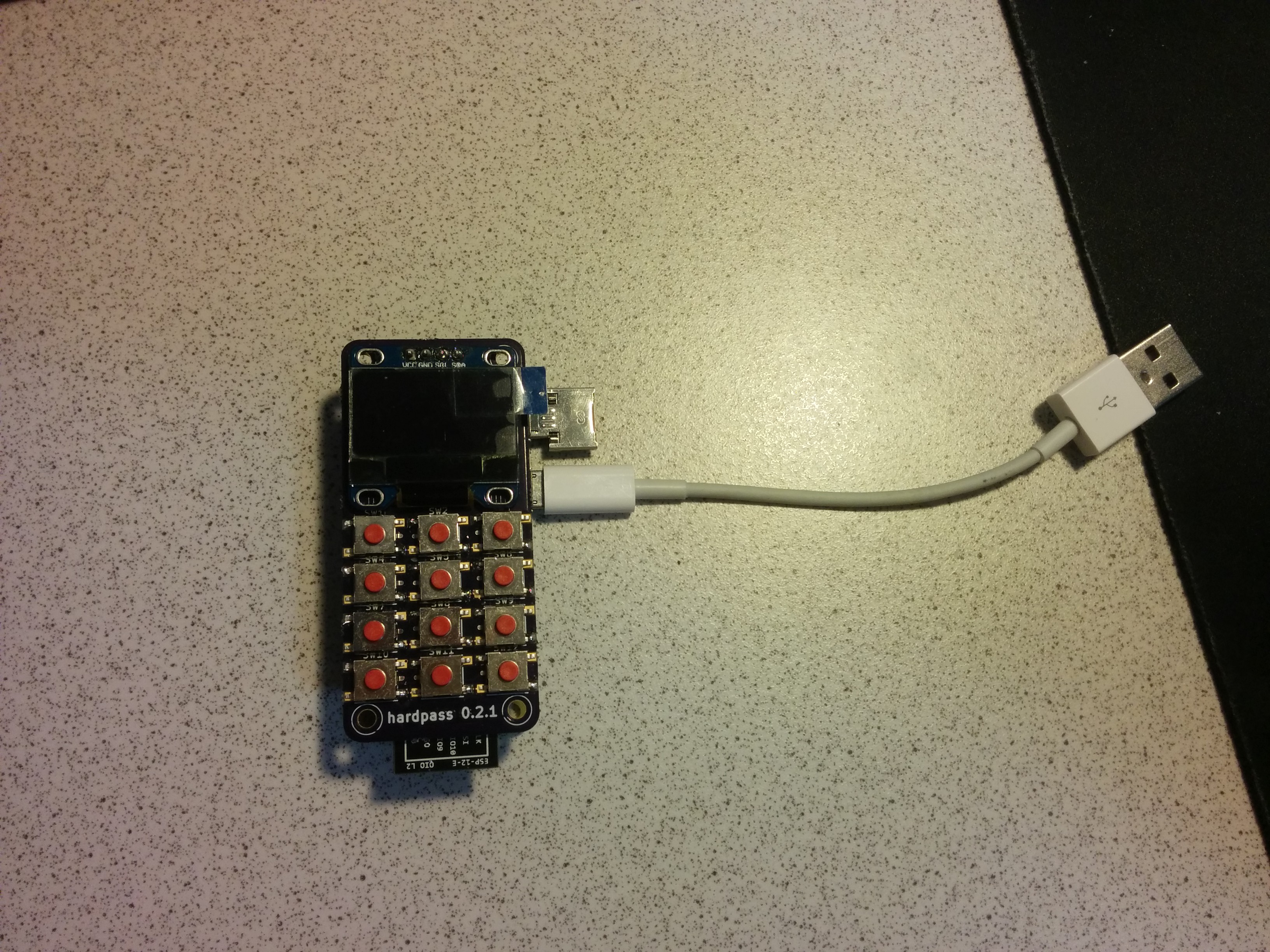
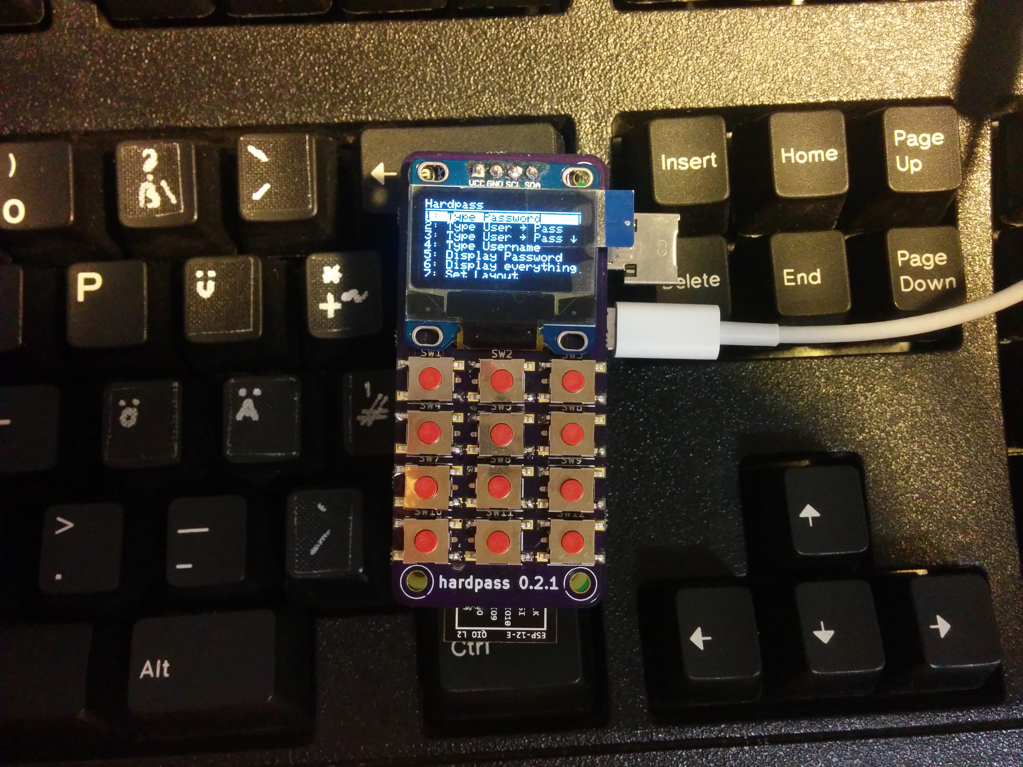
The front. I managed to squeze the ESP completely under the PCB in the `30pin` branch of the git repository.
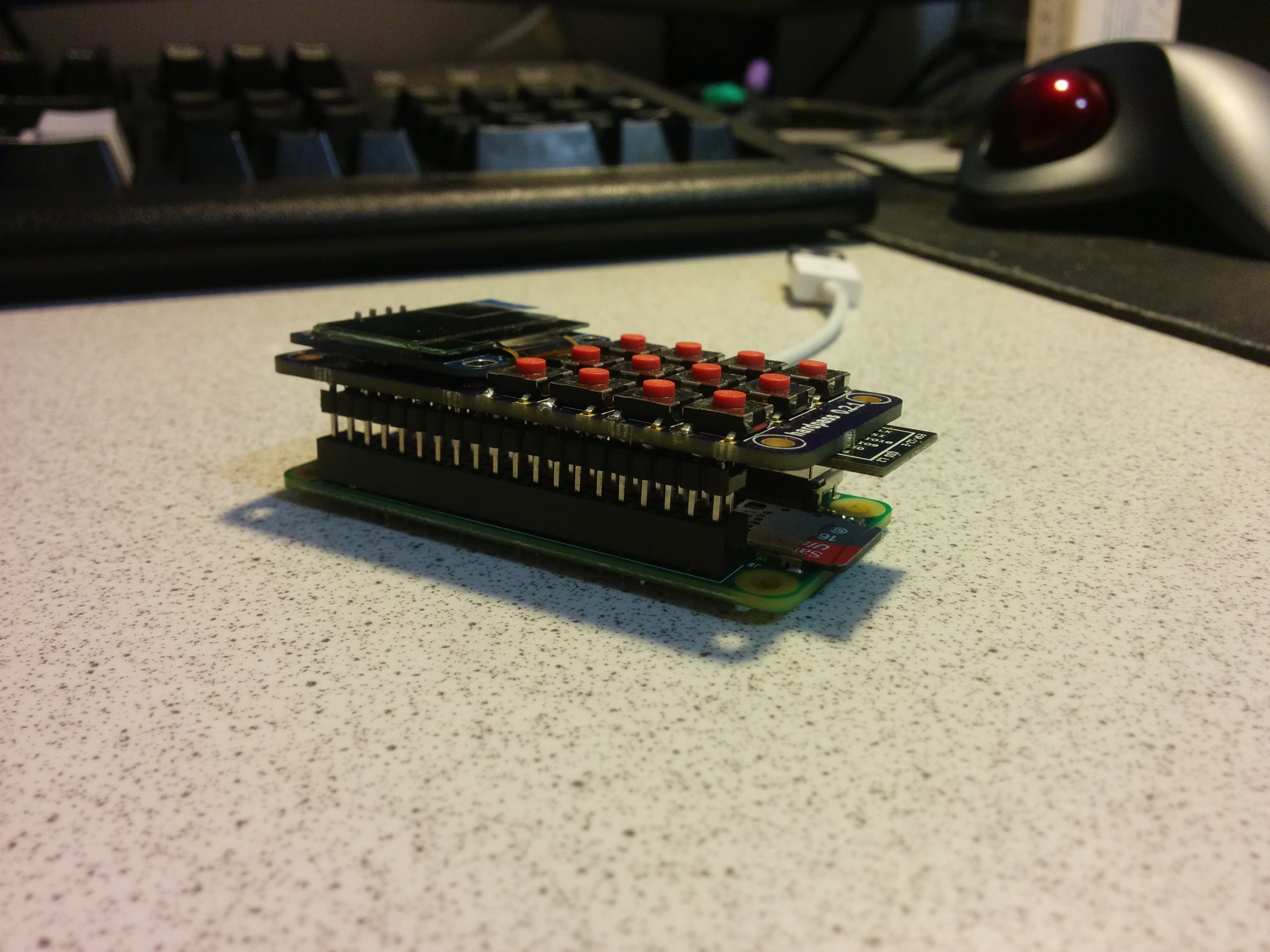
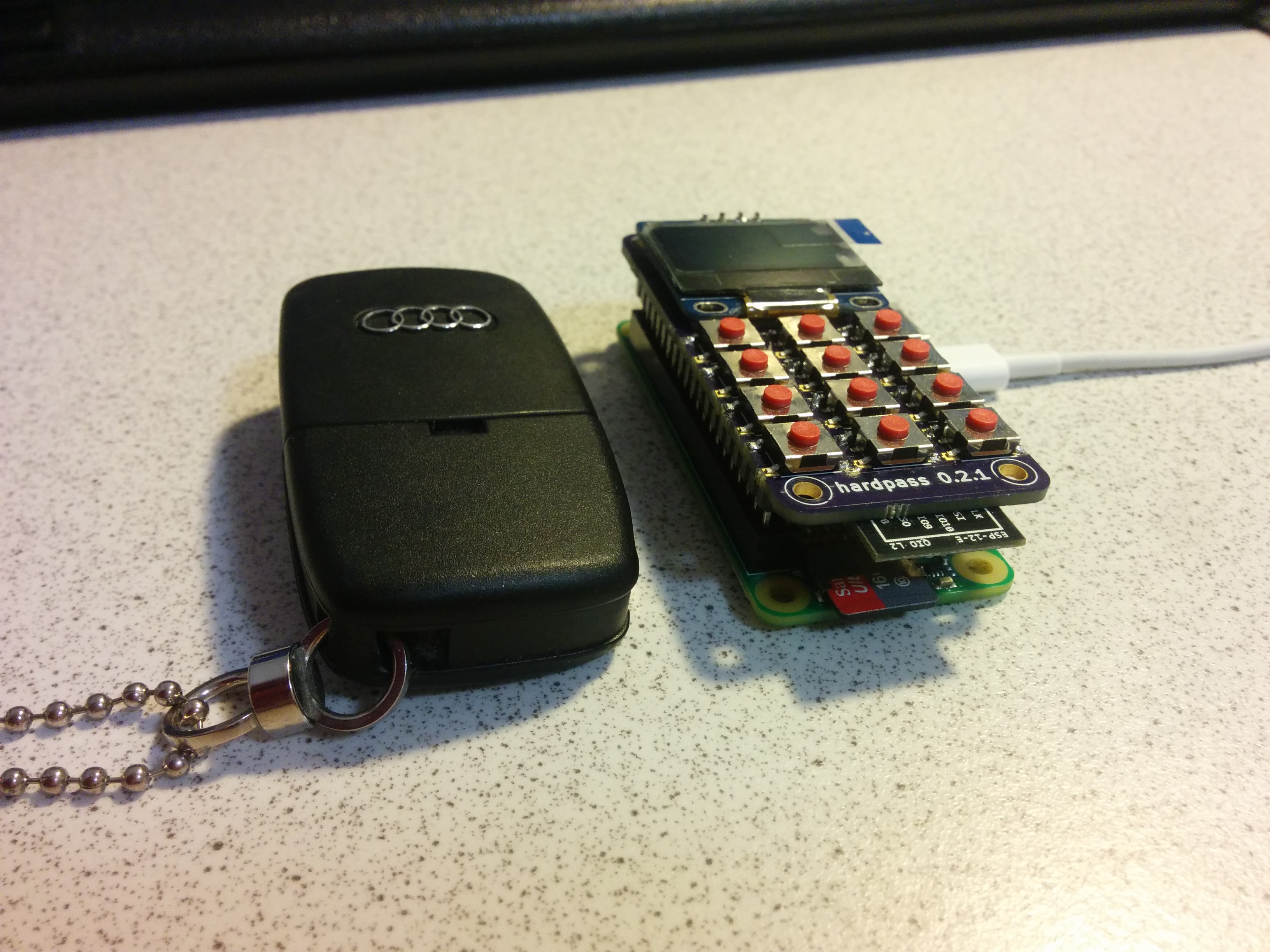
Since I don't want to sacrifice a Pi for each generation of the hardware, I opted to a header. The height is still tolerable even with the header and makes it about the size and thickness of a typical car keyfob.
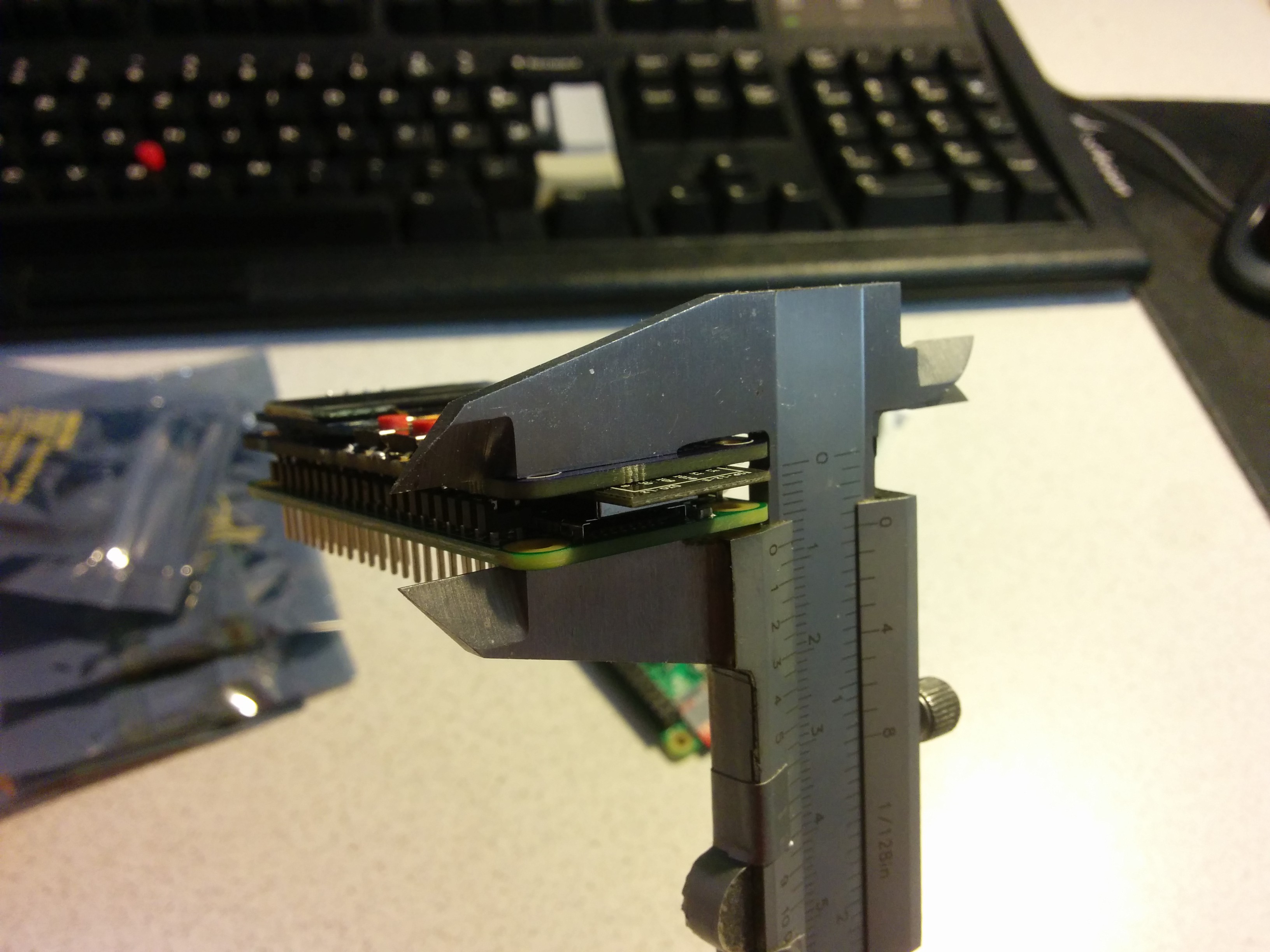
Without said header, the thickness can be reduced to roughly 8mm board-to-board. Then, the case of the ESP12 touches the SD card slot. I guess, one could remove that, but I haven't tried. (and yes, my shitty caliper broke and I fixed it with duct tape)
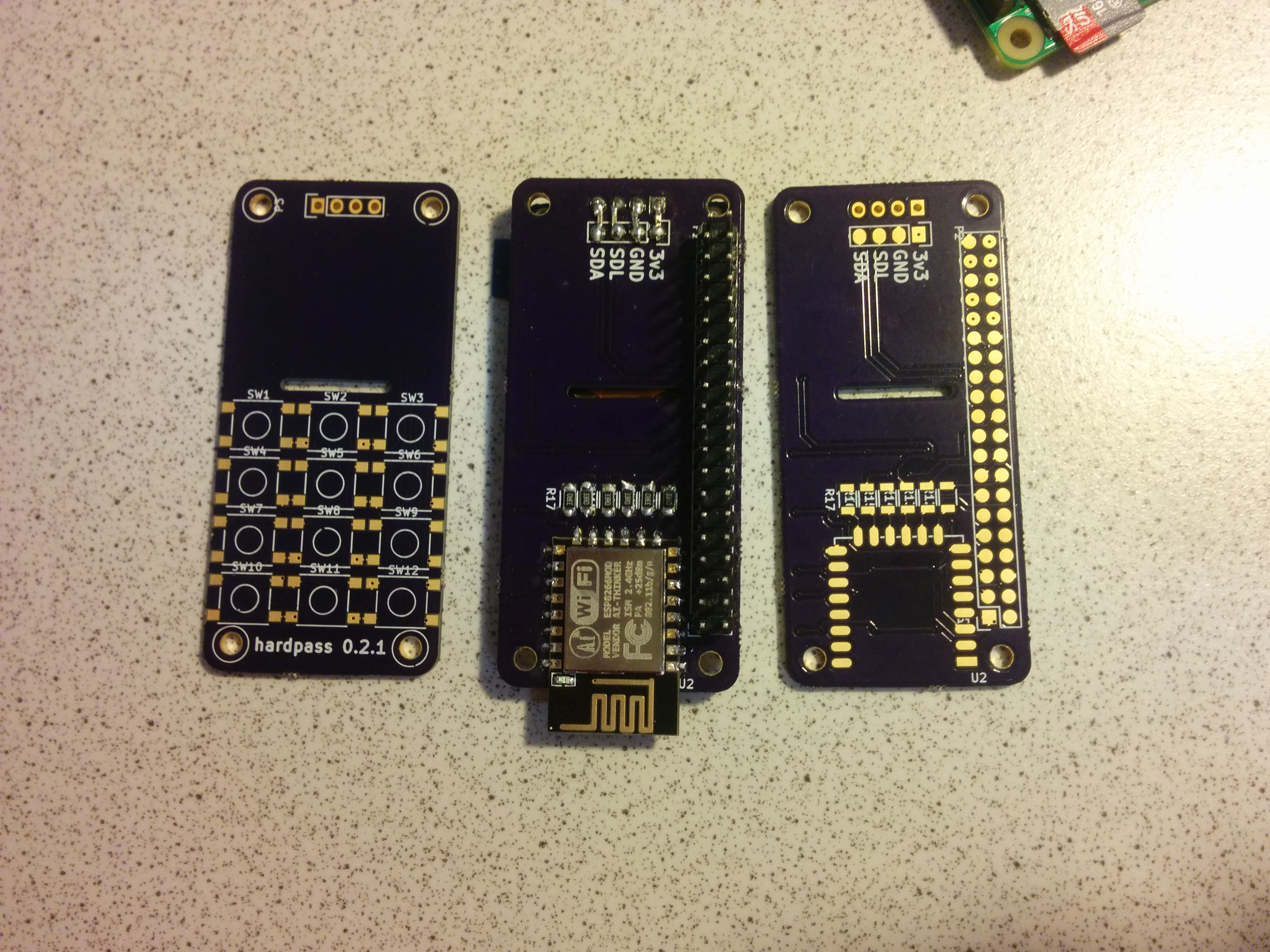
The board from the bottom. I bridged the OLED module over like this, because I couldn't remember the pinout of my module, and a search on AliExpress revealed, that they all have a different one.
As you can see, there isn't much space between the header and the ESP. This is the order of soldering I recommend: start with the header, then solder the ESP and its resistors, continue with the OLED and bridge it over, and finally solder the buttons (put it in a vice or in a Pi).
Hello world! this is the (already working) menu. use `*` as the up arrow, `#` as the down arrow, and `0` to select. I want to make the numbers jump directly to the `n`th item in the list, but that's on the todo list (as well as button debounce :S)
Discussions
Become a Hackaday.io Member
Create an account to leave a comment. Already have an account? Log In.